Timer Guide
1 Overview
Each timer group (Timer0 and Timer1) contains three timers, and every timer features a 32-bit up-counting counter.
All three counters in a group share a 4-bit prescaler.
Timers can generate interrupts after a programmed period or act as hardware clocks.
Demos and configuration: Timer demo and configuration guide
2 Features
Each TIMG module provides:
- 3 timers (Timer0/1/2)
- 3 independent 32-bit up-counters
- Real-time counter value readback
- 4-bit prescaler with division ratio 1–16
3 Functional Description
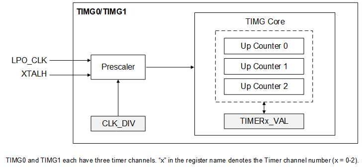
Figure 1. Timer group block diagram
Highlights:
- Clock selection and prescaler
  Each group can select LPO_CLK (32 kHz) or XTAL (26 MHz) as clock source via system configuration.
  A 4-bit prescaler divides the clock to generate the counter clock. Configure ``CLK_DIV`` to choose 1–16.

- 32-bit counters
  Three 32-bit up-counters with associated value registers. A counter starts when ``TIMERx_EN`` is set.
  In up-count mode the counter increments from 0 to ``TIMERx_VAL`` then wraps to 0 and raises an overflow event.

- Usage steps
  1) Configure the timer
     a. Select the clock source in the system module.
     b. Set ``CLK_DIV`` for the prescaler.
     c. Program ``TIMERx_VAL`` with the desired period.
  2) Enable the timer by setting ``TIMERx_EN``.
  3) Read the current count
     a. Select the timer via ``TIMERL_INDEX``.
     b. Set ``TIMERL_CNT_READ`` to latch the value.
     c. Read ``TIMERL_CNT`` for the latched count.

- Timer interrupt
  Enable ``TIMERx_INT`` to trigger an interrupt. Each level interrupt must be cleared by the CPU. After timeout, the interrupt stays asserted until explicitly cleared.