I2C User Guide
Summary
I2C is a serial synchronous half duplex communication protocol. Multiple hosts and slaves can be attached to the bus at the same time. I2C bus is composed of serial data line (SDA) and serial clock line (SCL). These wires need pull-up resistance.
I2C has the advantages of simplicity and low manufacturing cost, and is mainly used for short distance communication of low-speed peripheral devices (within one foot)
I2C Connection
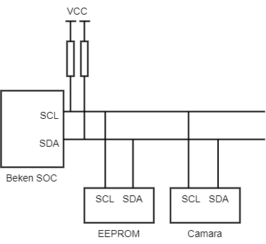
The above figure shows I2C hardware connection, in which:
SCL:Clock signal, which provides the clock for data transmission to synchronize data transmission
SDA:Used to transfer data.
BK7258 supports two I2Cs (I2C0 and I2C1).
I2C ID Description
I2C ID Allocation Rules
Beken I2C driver supports coexistence of hardware I2C and software simulated I2C. I2C ID is used to distinguish different I2C instances:
Hardware I2C: Uses SoC hardware I2C peripheral - ID Range:
0toSOC_I2C_UNIT_NUM - 1- For BK7258:id = 0, 1correspond to I2C0 and I2C1 - Features: Uses hardware registers, supports interrupt and DMA, high performanceSimulated I2C: Uses GPIO to simulate I2C timing in software - ID Range:
SIM_I2C_START_IDand above (typicallySIM_I2C_START_ID = SOC_I2C_UNIT_NUM) - For BK7258:id >= 2for simulated I2C - Features: Implemented via GPIO control, flexible configuration of any GPIO as SDA/SCL
ID Routing Mechanism
The unified API layer (i2c_unified.c) automatically routes to the corresponding implementation based on I2C ID:
id < SOC_I2C_UNIT_NUM→ Automatically uses hardware I2C driverid >= SIM_I2C_START_ID→ Automatically uses simulated I2C driver
Applications don’t need to worry about underlying implementation, just use the unified bk_i2c_\* API.
Note
When CONFIG_SIM_I2C is not enabled, only hardware I2C (id = 0, 1) is supported.
When CONFIG_SIM_I2C is enabled, both hardware I2C and simulated I2C can be used simultaneously.
Usage Notes
ID Selection: - For hardware I2C, use
id = 0orid = 1- For simulated I2C, useid >= 2(e.g.,id = 2, 3, ...) - Do not mix IDs outside the valid range at runtime, otherwiseBK_ERR_I2C_INVALID_IDerror will be returnedInitialization Order: - Must call
bk_i2c_driver_init()first to initialize the driver layer - Then callbk_i2c_init(id, cfg)for each I2C ID to be usedSimulated I2C Configuration: - Before using simulated I2C, enable
CONFIG_SIM_I2Cin Kconfig - ConfigureCONFIG_SIM_I2C0_SDA_GPIOandCONFIG_SIM_I2C0_SCL_GPIO(or I2C1 corresponding configuration) - Simulated I2C is protected by mutex to ensure thread safety, but performance is lower than hardware I2CError Handling: -
BK_ERR_I2C_INVALID_ID: ID is outside the valid range -BK_ERR_I2C_NOT_INIT: Driver not initialized -BK_ERR_I2C_ID_NOT_INIT: Specified ID not initialized
Example Code
// Initialize driver (call only once)
bk_i2c_driver_init();
// Use hardware I2C (id = 0)
i2c_config_t hw_i2c_cfg = {
.baud_rate = 100000,
.addr_mode = I2C_ADDR_MODE_7BIT,
.role = I2C_ROLE_MASTER,
};
bk_i2c_init(I2C_ID_0, &hw_i2c_cfg);
// Use simulated I2C (id = 2, requires CONFIG_SIM_I2C enabled)
#if CONFIG_SIM_I2C
i2c_config_t sim_i2c_cfg = {
.baud_rate = 100000,
.addr_mode = I2C_ADDR_MODE_7BIT,
.role = I2C_ROLE_MASTER,
};
bk_i2c_init(I2C_ID_2, &sim_i2c_cfg); // Automatically routes to simulated I2C
#endif
// Use unified API, no need to distinguish hardware/simulated
i2c_mem_param_t param = {
.dev_addr = 0x50,
.mem_addr = 0x0000,
.mem_addr_size = I2C_MEM_ADDR_SIZE_8BIT,
.data = buffer,
.data_size = 16,
.timeout_ms = 1000,
};
bk_i2c_memory_read(I2C_ID_0, ¶m); // Hardware I2C
bk_i2c_memory_read(I2C_ID_2, ¶m); // Simulated I2C (if enabled)
I2C Communication Flow
In master mode, the I2C interface initiates data transfer and generates a clock signal. Serial data transfer always begins with the appearance of a START bit (STA) and ends with the appearance of a STOP bit (STO). The start and stop bits are both generated by software in master mode. The START bit is generated by pulling the SDA line low while the SCL is high, and the STOP bit is generated by pulling the SDA line high while the SCL is high.
In slave mode, the interface is capable of recognizing its own address (7 or 10 bits) as well as a broadcast call address. Data and addresses are transmitted in 8-bit bytes, with the most significant bit (MSB) first. The address byte follows immediately after the START bit (a 7-bit address occupies one byte; a 10-bit address occupies two bytes). The address is always transmitted in master mode.
Transmission is ended by sending a STOP bit on the bus after an (N)ACK. After the STOP bit, any master device that wishes to initiate transfer on the bus may attempt to gain control of the bus. If the current master device wishes to initiate another transfer immediately after the current one, it can start a new transfer directly by sending a repeated START bit (Sr), rather than sending a STOP and then a START.
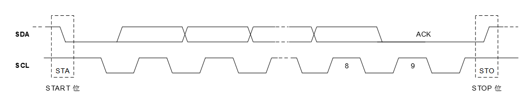
Figure 2. I2C_Communication Flow
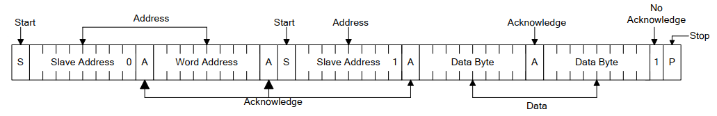
I2C sequence flow
The interface supports 7-bit and 10-bit addressing modes. The interface transmission timing under different addressing modes is shown in the following figure. In 7-bit addressing mode, the master device only needs to send 1 address byte after sending STA, with the content of SLV_ADDR[6:0]+W. In 10-bit addressing mode, the master device needs to send 2 address bytes after sending STA, with the first address byte containing 11110+SLV_ADDR[9:8]+W, and the second address byte containing SLV_ADDR[7:0].
The slave device detects STA and starts receiving address bytes. In 7-bit addressing mode, when the received first address byte matches the software-configured slave address, an interrupt is reported. In 10-bit addressing mode, only when the received first 2 address bytes match the software-configured slave address will an interrupt be reported, and the address bytes will not be written into the internal receive FIFO.
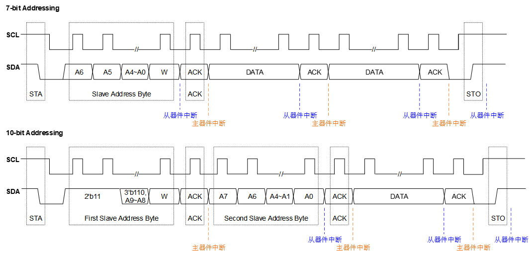
Figure 3. I2C_sequence_flow
Use of I2C
Beken I2C It can work in both master mode and slave mode. Whether the host or slave, you need to call ‘bk_i2c_init()’ to configure I2C before reading and writing. bk_i2c_init() It mainly configures the clock frequency of I2C SCL. If it works in slave mode, it also needs to configure the device address of Beken I2C.
Communication in I2C host mode
Call ‘bk_i2c_master_write()’ to write data to the slave device and ‘bk_i2c_master_read()’ to read data. For memory devices such as eeprom, Beken provides an A/B interface that can be assigned to the internal address of the slave device to perform read and write operations.For memory devices such as eeprom, Beken provides a ‘bk_i2c_memory_write()/bk_i2c_memory_read()’ interface that can be assigned to the internal address of the slave device to perform read and write operations.
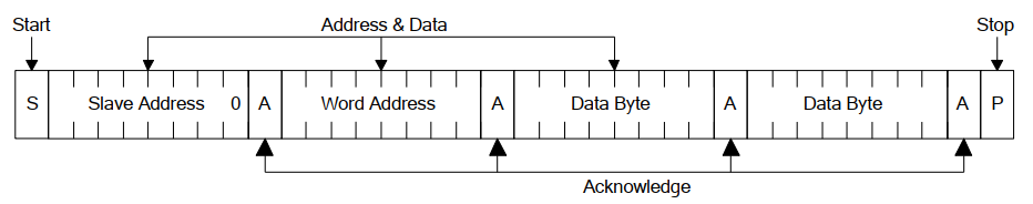
I2C memory write
I2C memory read
I2C communication in slave mode
For slave mode, Beken provides ‘bk_i2c_slave_write()/bk_i2c_slave_read()’ for sending/receiving data.