CAN
CAN Overview
The Controller Area Network (CAN) bus is a robust serial bus system that enables efficient and reliable communication among network nodes. It uses a multi-master configuration and handles error detection and recovery autonomously without host CPU intervention.
CAN Controller Features
CAN protocol support
CAN 2.0B (payload up to 8 bytes, verified against the Bosch reference model)
CAN FD (payload up to 64 bytes, ISO 11898-1:2015 compliant or non-ISO Bosch variant)
Programmable bit rates
CAN 2.0B data rate up to 1 Mbit/s
CAN FD data rate up to 2 Mbit/s
Programmable baud-rate prescaler (divider from 1 to 256). See the register definition and design documents for details.
Two transmit buffers
Primary transmit buffer (PTB)
Optional configurable secondary transmit buffer (STB)
User-selectable number of parameter slots
Default configuration is recommended.
FIFO or priority-decision mode
FIFO mode is used by default. Priority mode requires configuration; refer to the API.
Independent, programmable 29-bit acceptance filters
Configure the number of filters (1–16) via generic parameters.
Extended functionality
Single-shot transmission mode (PTB and/or STB)
Listen-only mode
Loopback mode (internal and external)
Transceiver standby mode
Extended status and error reporting
Records the last error type and arbitration-loss location
Programmable error warning limits
Configurable interrupt sources
By default only TX and RX callbacks are exposed to user applications.
Timestamping
Partial hardware support for ISO 11898-4 TTCAN
CiA 603 timestamping
Safety-related functions
ECC memory protection with address protection extension
Spatial redundancy inside the logic core
CAN 2.0 and CAN FD Frames
CAN FD is an extension of CAN 2.0. Main differences include:
Payload: CAN 2.0 up to 8 bytes; CAN FD up to 64 bytes
Bit rate: CAN 2.0 uses a single configurable bit rate; CAN FD uses two (slow arbitration phase and fast data phase)
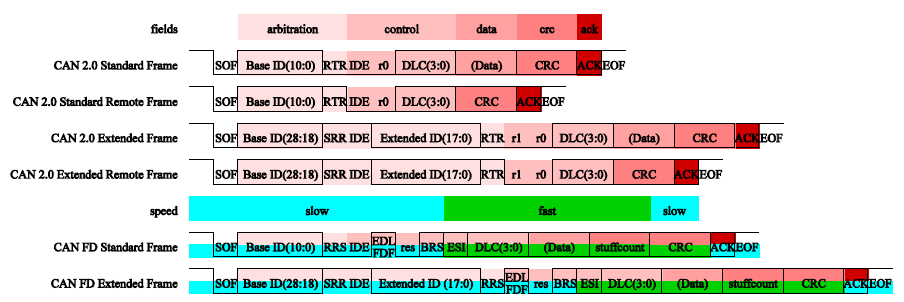
CAN 2.0 and CAN FD frame formats
Bosch’s non-ISO CAN FD specification uses the name EDL, while the ISO specification uses FDF for the same bit. Both terms are equivalent; this document uses FDF. In CAN FD ISO frames, the stuff count is part of the CRC field; in non-ISO frames it is not. CRC initialization also differs, so ISO and non-ISO frames are incompatible.
The CAN protocol engine inside the controller automatically sends and receives frames and provides the required control/status bits. The host selects the frame type (IDE, RTR, FDF), identifier, and payload.
Common abbreviations are listed below. Some bit names inherited from the CAN FD ISO specification have been retained for backward reference.
Acronym |
Description |
Notes |
|---|---|---|
ID |
Identifier |
|
RTR |
Remote Transmission Request |
Remote or data frame |
SRR |
Substitute Remote Request |
|
RRS |
Remote Request Substitution |
|
IDE |
Identifier Extension |
Standard or extended frame |
DLC |
Data Length Code |
Payload length |
EDL |
Extended Data Length |
CAN 2.0 vs CAN FD |
FDF |
FD Format Indicator (=EDL) |
CAN 2.0 vs CAN FD |
BRS |
Bit Rate Switch |
|
ESI |
Error State Indicator |
CAN Driver Configuration Macros
CONFIG_CAN: master switch (enables the core CAN driver,can_driver.c)CONFIG_CAN_TEST: enables test utilities (can_test.c). RequiresCONFIG_CAN=y.CONFIG_CAN_DEMO: enables demo examples (can_demo.c). RequiresCONFIG_CAN=y.
Typical combinations:
Driver only:
CONFIG_CAN=yAPI step-by-step testing:
CONFIG_CAN=yandCONFIG_CAN_TEST=yDemo validation:
CONFIG_CAN=yandCONFIG_CAN_DEMO=y
Key Data Structures
can_config_tprotocol– Select CAN 2.0B or CAN FD.s_speed– Slow speed. Low-speed mode (≤125 kbps) for low-cost, low-power scenarios.f_speed– Fast speed. Standard speed mode (≈500 kbps) for real-time, low-latency scenarios.tx_size– Depth of the software TX KFIFO that extends the hardware TX FIFO.rx_size– Depth of the software RX KFIFO that extends the hardware RX FIFO.can_frame_tag_tid– Identifier.ide– Identifier extension.rtr– Remote transmission request; only valid for CAN 2.0.fdf– FD format indicator (=EDL).brs– Bit-rate switch; only for CAN FD.esi– Error state indicator; only for CAN FD RX.ttsen– Time-triggered switch for CAN FD to trigger rate changes at scheduled times.can_frame_stag– Seecan_frame_tag_t.size– Payload size.data– Pointer to payload buffer.can_acc_mask_ide_eCAN_ACCEPT_BOTH– Accept standard and extended frames.CAN_ACCEPT_STANDARD– Accept standard frames only.CAN_ACCEPT_EXTENDED– Accept extended frames only.drv_switch_eDRIVER_DISABLE– Disable protocol switch.DRIVER_ENABLE– Enable protocol switch.can_acc_filter_cmd_saide– Seecan_acc_mask_ide_e.code– Identifier (≤29 bits).mask– Bit mask: 0=accept, 1=reject for the corresponding ID bits.seq– Filter index (0 to MAX_ACF_NUM, default 0 accepts all).onoff– Enable/disable; seedrv_switch_e.can_callback_des_tcb– Callback function pointer.param– Private parameter.
CAN API Usage
bk_err_t bk_can_init(can_dev_t *can);Initialize configuration. Review the data structures above.
bk_err_t bk_can_driver_init(void);Load the driver.
bk_err_t bk_can_driver_deinit(void);Unload the driver.
bk_err_t bk_can_deinit(void);Release configuration and resources.
bk_err_t bk_can_receive(uint8_t *data, uint32_t expect_size, uint32_t *recv_size, uint32_t timeout);Receive data into
data.expect_sizespecifies the requested length;recv_sizereturns the actual length;timeoutis the wait time. Reception can be interrupt-driven (upper/lower half) or blocking until data arrives.bk_err_t bk_can_send_ptb(can_frame_s *frame);Transmit via the primary TX buffer (PTB).
bk_err_t bk_can_send(can_frame_s *frame, uint32_t timeout);Transmit and wait for completion.
bk_err_t bk_can_acc_filter_set(can_acc_filter_cmd_s *cmd);Configure hardware acceptance filters to limit incoming IDs.
void bk_can_register_isr_callback(can_callback_des_t *rx_cb, can_callback_des_t *tx_cb);Register TX/RX interrupt callbacks. These run in interrupt context; keep handlers lightweight.
CAN Pin and GPIO Map
CAN Pin |
BK7258_CP0 |
|---|---|
CAN TX |
44 |
CAN RX |
45 |
CAN STBY |
46 |
Pins are multiplexed with other functions:
GPIO_44: SPI0_SCK (IO) / ADC0 (Z) / RGB_b[6] / I8080_d3 (O) / I2S2_SCK (IO)
GPIO_45: SPI0_NSS (IO) / ADC7 (Z) / RGB_b[5] / I8080_d2 (O) / I2S2_SYNC (IO)
GPIO_46: SPI0_MOSI (IO) / ENET_PHY_INT (I) / TOUCH[140] / RGB_b[4] / I8080_d1 (O) / I2S2_DIN (IO)