Introduction to the Software Mechanism and Interface Introduction of PWM LED Control Mechanism

[zh_CN]

Important

At present, the three-color LED pins in the default project of the SDK do not support PWM functionality.

Currently, the PWM project of the SDK is not open to users for modifying RGB values with external devices. If there is a development need, please contact the developers!

If PWM support is required, please refer to the pin diagram of the chip, and connect the RGB LED to the GPIO pins that the PWM1 register uses (for example, on the 7236, these are pins 32, 34, and 36).

Hardware configuration for a three-color LED light supporting PWM (Pulse Width Modulation)

We still take the double lamp 7236 module as an example to introduce the hardware configuration.

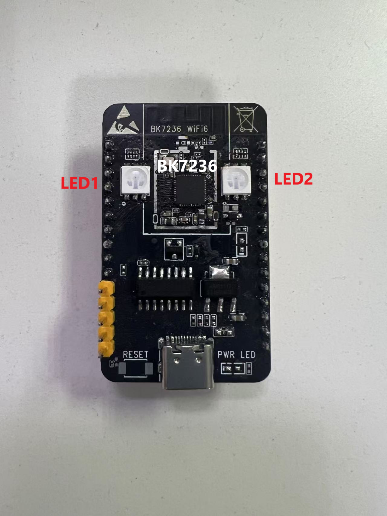
In this demo project, the BK7236 module is used as shown in the following figure:

bk7236

bk7236

In this module, the GPIO pin connected to the LED1 is controlled by the PWM1 register on the left, thus, LED1 supports PWM functionality.

Software configuration for a three-color LED light supporting PWM (Pulse Width Modulation)

The software running logic for a three-color LED light that supports PWM is identical to that of a regular three-color light. If you have not read the software design logic for the three-color LED light, please see :Introduction to the Software Mechanism and Interface of the RGB LED Lighting System for details. Below is an introduction to the PWM-specific part, which provides a simple explanation based on the 7236 module shown in the above image.

Introduction to PWM on RGB LED lights

PWM (Pulse Width Modulation) is a commonly used analog signal processing technology, which simulates analog signals of different intensities by controlling the width of pulse signals. In LED (light-emitting diode) applications, PWM is mainly used to adjust the brightness of LEDs.

Below are the main applications of PWM on LEDs:

  • Brightness Adjustment: By changing the duty cycle (the proportion of the pulse high level time to the overall cycle time) of PWM, the brightness of the LED can be controlled. The higher the duty cycle, the brighter the LED; the lower the duty cycle, the dimmer the LED.

  • Simulated Brightness: Although LEDs are digital devices, PWM can achieve effects similar to analog brightness adjustment. By changing the frequency and duty cycle of PWM, different brightness continuous changes can be produced.

  • Flicker Elimination: At low brightness, LEDs may flicker, which can be uncomfortable for people. By using PWM at an appropriate frequency (usually above a few thousand hertz), this flickering can be effectively eliminated.

  • Color Control: In RGB LED (red, green, blue light-emitting diode) applications, PWM can control the brightness of each color separately, thus achieving the adjustment of mixed light colors.

  • Image Display: In some special LED applications, such as LED displays, PWM can be used to control the brightness of each pixel, realizing the display of dynamic images.

In summary, PWM has a very wide range of applications in LEDs and is an important technology for adjusting LED brightness and color in modern electronic devices.

PWM LED implementation

demo:

components/demos/bk_mesh_led_demo_v2.c

Note

The PWM project is not applicable to the same engineering as the previous LED project. If you are using the PWM project, please use the following compilation command:

make bk7236 -j8 PROJECT=bk_mesh/pwm_led

Internal API used in the demo project

In the demo project, some internal PWM (Pulse Width Modulation) APIs from BK-IDK are used, and the introduction to these APIs is as follows:

Header File

Functions

bk_err_t bk_pwm_driver_init(void)

Init the PWM driver.

This API init the resoure common to all PWM channels:

  • Init PWM driver control memory

  • Configure PWM common clock to 26M

This API should be called before any other PWM APIs.

Returns

  • BK_OK: succeed

  • others: other errors.

bk_err_t bk_pwm_init(pwm_chan_t chan, const pwm_init_config_t *config)

Init the PWM channel.

This API init the PWM channel:

  • Power up the PWM channel

  • Configure the PWM channel clock to 26M

  • Map the PWM channel to dedicated GPIO port

  • Set the period and duty cycle.

For duty/cycle relationship, refer to bk_pwm_set_period_duty()

Returns

  • BK_OK: succeed

  • BK_ERR_PWM_NOT_INIT: PWM driver not init

  • BK_ERR_NULL_PARAM: config is NULL

  • BK_ERR_PWM_CHAN_ID: invalid PWM channel

  • BK_ERR_PWM_PERIOD_DUTY: PWM duty/period relationship is invalid

  • others: other errors.

bk_err_t bk_pwm_start(pwm_chan_t chan)

Stop a PWM channel.

This API init the resoure common to all PWM channels:

  • Init PWM driver control memory

  • Configure PWM common clock to 26M

Returns

  • BK_OK: succeed

  • others: other errors.

bk_err_t bk_pwm_stop(pwm_chan_t chan)

Stop a PWM channel.

This API init the resoure common to all PWM channels:

  • Init PWM driver control memory

  • Configure PWM common clock to 26M

Returns

  • BK_OK: succeed

  • others: other errors.

bk_err_t bk_pwm_set_period_duty(pwm_chan_t chan, pwm_period_duty_config_t *config)

Configure the PWM period and duty cycle.

This API is used to configure the period and duty time. The unit is cycle of PWM channel clock, since the PWM channel clock is default to 26M, the unit is 1/26M (1/26 000 000) seconds.

The beken chip supports up to 3 duties, the exact duty numbers depends on the target type.

EXample1 - the simplest case::

Clock cycle = 1/26M
Initial signal is High
duty_cycle = D1 = 3
duty2_cycle = 0
duty3_cycle = 0
period_cycle = 3 + 2 = 5

                  |<-C->|
                   __    __    __    __    __    __    __    __    __    __    __    __
Clock Signal:   __|  |__|  |__|  |__|  |__|  |__|  |__|  |__|  |__|  |__|  |__|  |__|  |__
                  __________________             _________________             ___________
PWM Signal:    __|                  |___________|                 |___________|

Duty1:           |<------- D1 ----->|

Period:          |<---------- Period1 --------->|<------ Period2 ------------>|

Example2 - 3 duty with initial signal high::

Clock cycle = 1/26M
Duty_cycle = D1 = 1
Duty2_cycle = D2 = 2
Duty3_cycle = D3 = 3
period_cycle = D1 + D2 + D3 = 6

                  |<-C->|
                   __    __    __    __    __    __    __    __    __    __    __    __    __
Clock Signal:   __|  |__|  |__|  |__|  |__|  |__|  |__|  |__|  |__|  |__|  |__|  |__|  |__|
                  ______             _________________ _____             _________________
PWM Signal:    __|      |___________|                 |     |___________|                 |__

Duty1:           |<-D1->|<----D2--->|<------D3------->|

Period:          |<--------------- Period1 ---------->|<------------ Period2 ------------>|

Example3 - 3 duty with initial signal low::

Clock cycle = 1/26M
Duty_cycle = D1 = 1
Duty2_cycle = D2 = 2
Duty3_cycle = D3 = 3
period_cycle = D1 + D2 + D3 = 6

                  |<-C->|
                   __    __    __    __    __    __    __    __    __    __    __    __    __
Clock Signal:   __|  |__|  |__|  |__|  |__|  |__|  |__|  |__|  |__|  |__|  |__|  |__|  |__|
                __       ___________                         ___________
PWM Signal:       |_____|           |_________________|_____|           |_________________|__

Duty1:           |<-D1->|<----D2--->|<------D3------->|

Period:          |<--------------- Period1 ---------->|<------------ Period2 -------------|

Example4 - 3 duty with initial signal low and period > (D1 + D2 + D3)::

Clock cycle = 1/26M
Duty_cycle = D1 = 1
Duty2_cycle = D2 = 2
Duty3_cycle = D3 = 3
period_cycle = D1 + D2 + D3 + 1 = 7

                  |<-C->|
                   __    __    __    __    __    __    __    __    __    __    __    __    __
Clock Signal:   __|  |__|  |__|  |__|  |__|  |__|  |__|  |__|  |__|  |__|  |__|  |__|  |__|
                __       ___________                   _____       ___________
PWM Signal:       |_____|           |_________________|     |_____|           |______________

Duty1:           |<-D1->|<----D2--->|<------D3------->|

Period:          |<--------------- Period ----------------->|

Attention

1. The period should great or equal to (D1 + D2 + D3)

Attention

2. If the duty Dx is 0, then Dx+1 to D3 should also be 0. If D1 is 0, it indicates the duty ratio is 0% and the signal is always low.

Attention

3. If D1 equals period, it indicates the duty ratio is 100% and the signal is always high.

Attention

4. The signal strengh between two successive duties is opposite, e.g. if signal of D1 is high, then signal of D2 is low.

Attention

5. The initial signal is the signal strengh of D1 if D1 is not 0.

Attention

6. The duty/period configuration is very flexible, different configurations may have same result.

Returns

  • BK_OK: succeed

  • BK_ERR_NULL_PARAM: config is NULL

  • BK_ERR_PWM_CHAN_NOT_INIT: PWM channel not init

  • BK_ERR_PWM_CHAN_ID: invalid PWM channel

  • BK_ERR_PWM_PERIOD_DUTY: PWM duty/period relationship is invalid

  • others: other errors.

The external API used in the demo project

The software design for the PWM engineering is the same as that for the common LED three-color lights. The PWM engineering also requires the registration of external APIs. The interface for the external API is as follows:

Header File

Functions

int bk_mesh_256led_demo_set_vendor_info(uint8_t *vendor_ptr, uint8_t type, uint8_t layer)

APP set PWM LED Color and blink time.

Parameters
  • vendor_ptr – vendor_ptr is the pointer formatted by Vendor format,it contains the RGB value and blink time

  • type – type is not use, the parameter is retained to align with the global variable function pointer

  • layer – layer is not use, the parameter is retained to align with the global variable function pointer

Returns

  • BK_OK: succeed

  • others: other errors

uint8_t *bk_mesh_256led_demo_get_vendor_info(struct bk_mesh_256_color_light_msg *led_info, uint8_t *len)

APP get PWM LED Color and blink time.

Parameters
  • led_info – led_info is the pointer of struct bk_mesh_256_color_light_msg,it contains the RGB value and blink time

  • len – len is used for BK MESH NET to used to form a reply frame

Returns

  • reply frame head ptr

int bk_mesh_256_led_demo_inform_vendor_info(uint8_t type, uint8_t layer)

SDK set PWM LED Color and blink time through specified events.

Parameters
  • type – type is the event type

  • layer – layer is the specified layer.diff layer shows diff color and blink time

Returns

  • BK_OK: succeed

  • others: other errors

int bk_mesh_pwm_led_init()

pwm led init.

Returns

  • BK_OK: succeed

  • others: other errors

Note

The specific implementations of these functions can be carried out by the customer themselves, or functions that have already been written in the demo can be used.

These functions are just the specific implementation of the settings for the PWM LED. What we need to do next is to unify these APIs to the corresponding vendor APIs.

Just like in the LED tri-color lamp project, all the vendor information is stored under the global structure g_vendor_info , and for the PWM project, what we need to focus on is the struct bk_mesh_256_color_light_msg led_256_control .

The definition of the structure struct bk_mesh_256_color_light_msg is as follows:

Header File

Structures

struct bk_mesh_256_color_light_msg

Public Members

u8 type_msg

SDK event type

u8 layer

SDK layer

u16 time

LED Blink time

u8 bitmap[3]

PWM LED RGB Value

pwm_period_duty_config_t red_config

Red Value for duty and cycle

pwm_period_duty_config_t green_config

Green Value for duty and cycle

pwm_period_duty_config_t blue_config

Blue Value for duty and cycle

The explanations for each member are as follows:

member

Type

Explanation

type_msg

u8

The message type configured last time, used in the inform function.

layer

u8

The hierarchical information of the last configuration is used in the inform function.

time

u16

The last configured blink time

bitmap

u16[3]

The last configured RGB values, where R, G, B are from low to high (temporarily stored in the middle, not representing the final configuration value).

red_config

pwm_period_duty_config_t

The last configured R value includes the number of cycles and the duty ratio.

green_config

pwm_period_duty_config_t

The last configured G value includes the number of cycles and the duty ratio.

blue_config

pwm_period_duty_config_t

The last configured B value includes the number of cycles and the duty ratio.

For the explanation of pwm_period_duty_config_t, please refer to the following URL:

Additionally, in order to characterize the compiled version that supports PWM projects, the following operations need to be performed in the initialization function:

g_vendor_info.vendor_bitmap |= BK_MESH_DEMO_SUPPORT_PWM_LED;

Among them, BK_MESH_DEMO_SUPPORT_PWM_LED occupies BIT2 in the Bitmap, which is currently used for the internal message mechanism. If users need to set it in the external APP, please refer to the TODO Developer Documentation!

Note

To use PWM engineering, you need to enable CONFIG_BK_WIFI_MESH_DEMO_PWM_LED, and it is important to note that only LED1 supports PWM, while LED2 only supports single-color configuration. In the case of using the double-LED bk7236 hardware module, there is no need to enable CONFIG_BK_WIFI_MESH_DEMO_LED. This macro is prepared for the single-LED hardware group.

Registering public APIs used in the demo project

Similar to the LED tri-color light engineering, the external API used in the PWM LED engineering mentioned above is also from the unified external API provided by the vendor. 
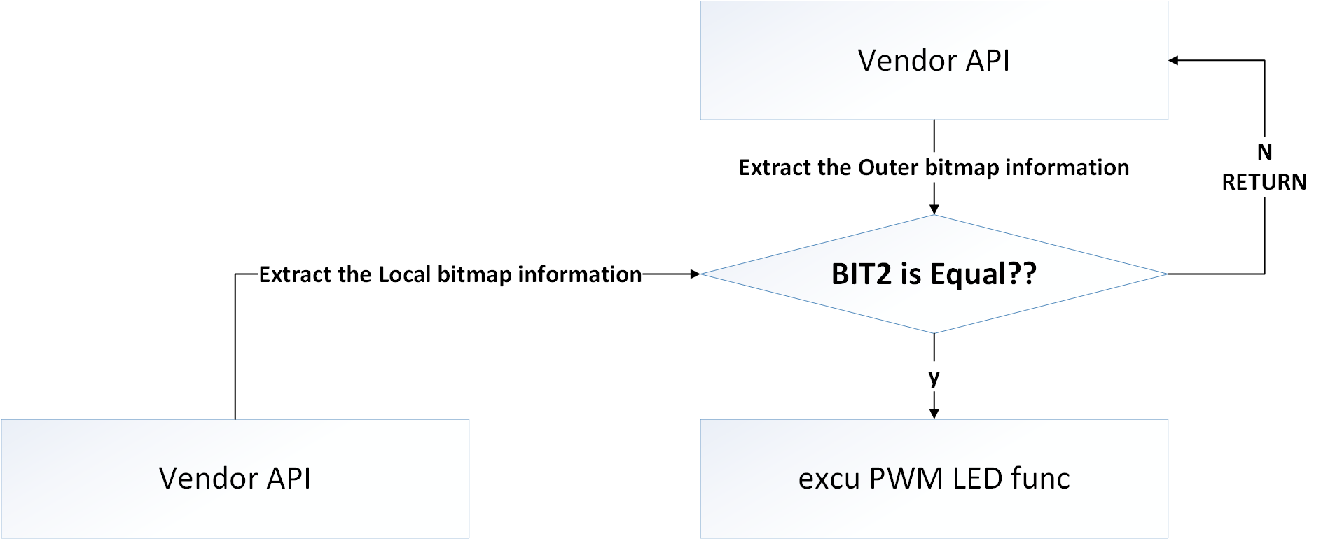
The overall process of determining which engineering to execute is by comparing the internal bit values stored in g_vendor_info.vendor_bitmap with the external bit values carried by the Vendor API (of course, there are also corresponding macros for protection). The following figure is an internal execution flowchart of the Vendor API for the PWM engineering.

Vendor API flow for PWM

Vendor API flow for PWM

Note

The set vendor function is currently supported internally in the SDK, but the mobile APP provided by Beken does not support configuration, therefore, the default SDK does not support PWM LED configuration!

If necessary, you can implement the APP-side settings yourself or contact the developer!

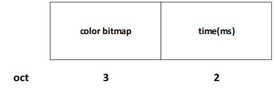
The format of the Vendor field in the external message area used in the demo project

The PWM LED project uses the Vendor field format in the external message area that is the same as the tri-color LED project, but with the following distinctions:

- The PWM LED project uses BIT2 in the bitmap as a marker.
  • The PWM LED project uses the Bitmap2 Content field.

Below is an introduction to the Vendor field format related to the PWM LED project.

Bitmap2

  • Bitmap0 is currently being used by the PWM LED project. For communication between user external devices and nodes, if it involves PWM LED interaction, this bit needs to be set to 1.

    • When this bit is set to 1, it indicates that this command supports PWM LED control.

    • When this bit is set to 0, it indicates that this command does not support PWM LED control.

Note

This field is effective when configured as true under the condition of CONFIG_BK_WIFI_MESH_DEMO_PWM_LED !

Bitmap2 Content

Note

This field is effective when configured as true under the condition of CONFIG_BK_WIFI_MESH_DEMO_PWM_LED !

Bitmap2 Content:

vendor_bitmap0

PWM Bitmap2 COntent

Below is an introduction to the meanings of various fields within the Bitmap2 Content:

  • color bitmap:The color to be configured or queried, under the PWM LED project, is in the mode where RGB each occupies one byte,

    so the length is 3 bytes. Therefore, the format of this field is as follows:

    pwm led_color_bitmap

    pwm color bitmap

  • time: The flashing time for the color to be configured or queried

    This field configures the flashing time, with the unit being milliseconds. When this value is not 0, the LED light will flash by default

Internal state setting mechanism

The following table lists the internal messages currently in use:

Enum

Explanation

NODE_POWER_ON

Node Power On

NODE_START_NET

Node Start mesh netting

NODE_NET_FAIL

mesh netting failed

NODE_NET_LAYER

Color configuration based on hierarchy, SDK default, see the table below.

NODE_BREAKDOWN

Node Failure

NODE_REVOVER

Node Recover

NODE_LAYER_CHANGE

Change node layer

NODE_STOP

Node Stop

he current default level-color contrast table of the SDK:

Layer

Color

1

red

2

green

3

blue

4

yellow

5

magenta

6

cyan

Special event color:

Event

Color

NODE_POWER_ON

white

NODE_BREAKDOWN

Current color blinking

NODE_STOP

white