Introduction to the Software Mechanism and Interface of the RGB LED Lighting System

[zh_CN]

Important

Currently, the general three-color LED light project of the SDK is the default project, and its used external project macro BK_MESH_DEMO_SUPPORT_PWM_LED is set to default as ‘y’. The general three-color LED light project of the SDK does not support PWM! Please refer to :Introduction to the Software Mechanism and Interface Introduction of PWM LED Control Mechanism for PWM project configuration and implementation.

Hardware configuration of the RGB LED Lighting System

The SDK uses an internal test module to test a common three-color he RGB LED Lighting System project.

As shown in the figure below, it uses the BK7236 module:

bk7236

Three-color he RGB LED Lighting System project bk7236 module

The following chart shows the GPIO pin configuration for the default ordinary Three-color RGB LED Lighting System engineering of the SDK:

Color pin | GPIO pin

BK_MESH_PWM_RED_PIN

18

BK_MESH_PWM_GREEN_PIN

24

BK_MESH_PWM_BLUE_PIN

19

Configurations of GPIO pins for hree-color he RGB LED Lighting System project.

Note

Please ensure that the configuration is set below BK_MESH_DEMO_SUPPORT_PWM_LED !

Software Configuration for Three-color RGB LED Lighting System

The software configuration for Three-color RGB LED Lighting System follows the Vendor’s software configuration as well, i.e., it occupies the bit0 position of the Vendor Bitmap and the Bitmap0 Content field. Of course, the default field design of the SDK merely provides a method of implementation, allowing users to design the content of the Bitmap0 Content themselves. Below, I will introduce the default design form of the SDK.

Three-color RGB LED Lighting System implementation

demo path:

components/demos/bk_mesh_led_demo.c

Note

The Three-color RGB LED Lighting System is supported by default, and the compilation command is as follows (the part in parentheses is optional):

make bk7236 -j8 (PROJECT=bk_mesh/3_led)

Internal API used for Three-color RGB LED Lighting System

In the demo project, we only use the introductions of these APIs as follows:

Header File

Functions

bk_err_t bk_alarm_register(aon_rtc_id_t id, alarm_info_t *alarm_info_p)

timer API

Register an alarm to AON_RTC id timer !!! NOTES: the callback function is in ISR, so can’t block too much time. F.E:can’t call sleep/suspend; !!! !!! NOTES: freertos forbid call free/malloc in ISR which include suspend and resume. !!! @id: register to which aon_rtc id

Parameters

alarm_info_p – includes below info: name_p: the name of the registered alarm period_time: what’s the alarm time, milliseconds * AON_RTC_MS_TICK_CNT period_cnt: 0xFFFFFFF means always period until user unregister it, or means period how many times callback: if the alarm comes, will call this callback param_p: the param will be used for callback

Returns

  • BK_OK: succeed

  • others: other errors.

bk_err_t bk_alarm_unregister(aon_rtc_id_t id, uint8_t *name_p)

Unregister an alarm from AON_RTC id timer.

Attention

1. Please don’t unregister self in the alarm’s callback.

Parameters
  • id – unregister the aon_rtc id alarm

  • name_p – the name of the registered alarm which will be unregistered.

Returns

  • BK_OK: succeed

  • others: other errors.

Structures

struct _alarm_info_t

Public Members

uint8_t name[ALARM_NAME_MAX_LEN + 1]

TIMER NAME

uint32_t period_tick

TIMER TICK

uint32_t period_cnt

TIMER CNT, total period count == 0Xffffffff means forever period;else period how many times aon_rtc_isr_t callback; /**< TIMER CALLBACK FUNC

void *param_p

TIMER CALLBACK FUNC PARAMS

Type Definitions

typedef struct _alarm_info_t alarm_info_t

Additionally, for GPIO operations, macro functions can be directly used to complete them:

- #define BK_MESH_GPIO_UP(id) *(volatile uint32_t*) (SOC_AON_GPIO_REG_BASE + ((id) << 2)) = 2

- #define BK_MESH_GPIO_DOWN(id) *(volatile uint32_t*) (SOC_AON_GPIO_REG_BASE + ((id) << 2)) = 0

API used for the engineering of Three-color RGB LED Lighting System

The engineering API interface for Three-color RGB LED Lighting System is as follows:

Header File

Functions

int bk_mesh_led_demo_set_vendor_info(uint8_t *vendor_ptr, uint8_t type, uint8_t layer)

APP set LED Color and blink time.

Parameters
  • vendor_ptr – vendor_ptr is the pointer formatted by Vendor format,it contains the RGB value and blink time

  • type – type is not use, the parameter is retained to align with the global variable function pointer

  • layer – layer is not use, the parameter is retained to align with the global variable function pointer

Returns

  • BK_OK: succeed

  • others: other errors

uint8_t *bk_mesh_led_demo_get_vendor_info(struct bk_mesh_light_msg *led_info, uint8_t *len)

APP get LED Color and blink time.

Parameters
  • led_info – led_info is the pointer of struct bk_mesh_256_color_light_msg,it contains the RGB value and blink time

  • len – len is used for BK MESH NET to used to form a reply frame

Returns

  • reply frame head ptr

int bk_mesh_led_demo_inform_vendor_info(uint8_t type, uint8_t layer)

SDK set LED Color and blink time through specified events.

Parameters
  • type – type is the event type

  • layer – layer is the specified layer.diff layer shows diff color and blink time

Returns

  • BK_OK: succeed

  • others: other errors

int bk_mesh_light()

led init.

Returns

  • BK_OK: succeed

  • others: other errors

Note

The specific implementation of these functions can be done by the client themselves, or functions already written in the demo can be used.

These functions are merely the specific implementation settings within Three-color RGB LED Lighting System. What we need to do next is to unify these APIs to the corresponding vendor APIs.

All vendor information is stored under the global structure named g_vendor_info , while in the cThree-color RGB LED Lighting System, what we need to focus on is the struct bk_mesh_light_msg led_control .

struct bk_mesh_light_msg:

Header File

Structures

struct bk_mesh_light_msg

Public Members

u8 type_msg

SDK event type

u8 layer

SDK layer

u16 time

LED Blink time

u16 color_value

LED color value

u8 color_id

LED color id(internal use)

Each member’s explanation is as follows:

variable

Type

Explanation

type_msg

u8

The message type configured in the last setup, used in the inform function.

layer

u8

The hierarchical information from the last configuration is used in the inform function.

time

u16

The last configured blink time

color_value

u16

The last configured color value

Additionally, the following operations need to be performed in the initialization function:

g_vendor_info.vendor_bitmap |= BK_MESH_DEMO_SUPPORT_LED;

Among them, BK_MESH_DEMO_SUPPORT_LED occupies BIT0 in the Bitmap!

Note

Three-color RGB LED Lighting System requires enabling CONFIG_BK_WIFI_MESH_DEMO_LED!

Registration of the external API used in the Three-color RGB LED Lighting System

The overall process of the external API is determined by comparing the internal bit values stored in g_vendor_info.vendor_bitmap with the external bit values carried by the Vendor API, to decide which project to execute (of course, there are also corresponding macros for protection). The following illustration shows the internal execution flow chart of the Vendor API for a common three-color LED lamp:

Vendor API flow for LED

Vendor API flow for LED

Format of the Vendor field in the external message area used in the demo project

The format of the Vendor field used in the message area for Three-color RGB LED Lighting System is as follows:

- In the Three-color RGB LED Lighting System, BIT0 in the bitmap is used as a marker.
  • The Three-color RGB LED Lighting System uses the Content field of bitmap0.

Below is an introduction to the format of the Vendor field related to Three-color RGB LED Lighting System.

Bitmap0

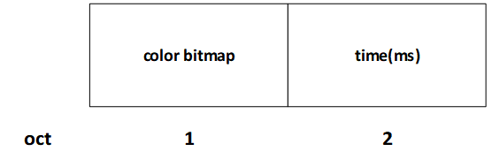
  • Bitmap0 is currently used in Three-color RGB LED Lighting System, for communication between users’ external devices and nodes. If PWM LED interaction is involved, this bit needs to be set to 1.

    • When this bit is 1, it indicates that this command supports LED control.

    • When this bit is 0, it indicates that this command does not support LED control.

Note

This field takes effect when it is CONFIG_BK_WIFI_MESH_DEMO_LED configured as true!

Bitmap0 Content

Note

This field takes effect when it is CONFIG_BK_WIFI_MESH_DEMO_LED configured as true!

Bitmap0 Content:

vendor_bitmap0

vendor_bitmap0

Below is an introduction to the meanings of each field within the vendor_bitmap0:

  • color bitmap:The color to be configured or queried, as the RGB three-color LED does not support PWM, the color is limited to 7 options.

    Therefore, the length of this field is 1 byte, and the format of this field is as follows:

    3led_color_bitmap

    color_bitmap

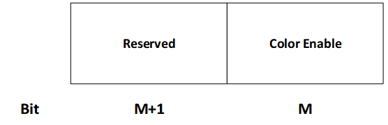
    Throughout the bitmap, the enable bits representing the three primary colors (Red, Green, Blue) from low to high are arranged. Currently, in order to expand, each primary color group occupies two bits, with its structure shown as follows:

    3led_rgbbit

    The structure diagram of the enable bit for the primary color group

From the above figure, it can be seen that at present, each primary color’s enable only occupies the low bit positions of the enable group, with the high bit positions reserved.

Internal state setting mechanism

The following table lists the internal messages currently in use:

Enum

Explanation

NODE_POWER_ON

Node Power On

NODE_START_NET

Node Start mesh netting

NODE_NET_FAIL

mesh netting failed

NODE_NET_LAYER

Color configuration based on hierarchy, SDK default, see the table below.

NODE_BREAKDOWN

Node Failure

NODE_REVOVER

Node Recover

NODE_LAYER_CHANGE

Change node layer

NODE_STOP

Node Stop

he current default level-color contrast table of the SDK:

Layer

Color

1

red

2

green

3

blue

4

yellow

5

magenta

6

cyan

Special event color:

Event

Color

NODE_POWER_ON

white

NODE_BREAKDOWN

Current color blinking

NODE_STOP

white