支持PWM的三色LED灯的软硬件机制和接口介绍
重要
目前SDK的默认工程的三色灯引脚不支持PWM功能
目前SDK的PWM工程的目前未开放用户使用外部设备修改RGB值,如有开发需求,请联系开发人员!
如需支持PWM,请参考芯片的引脚图,将LED三色灯与PWM1寄存器使用的GPIO引脚相连(例如在7236上,为32,34,36三个引脚)
支持PWM的三色LED灯的硬件配置
我们仍以双灯7236模组为例子,介绍一下硬件配置
本次demo工程中使用BK7236模组如下图所示:
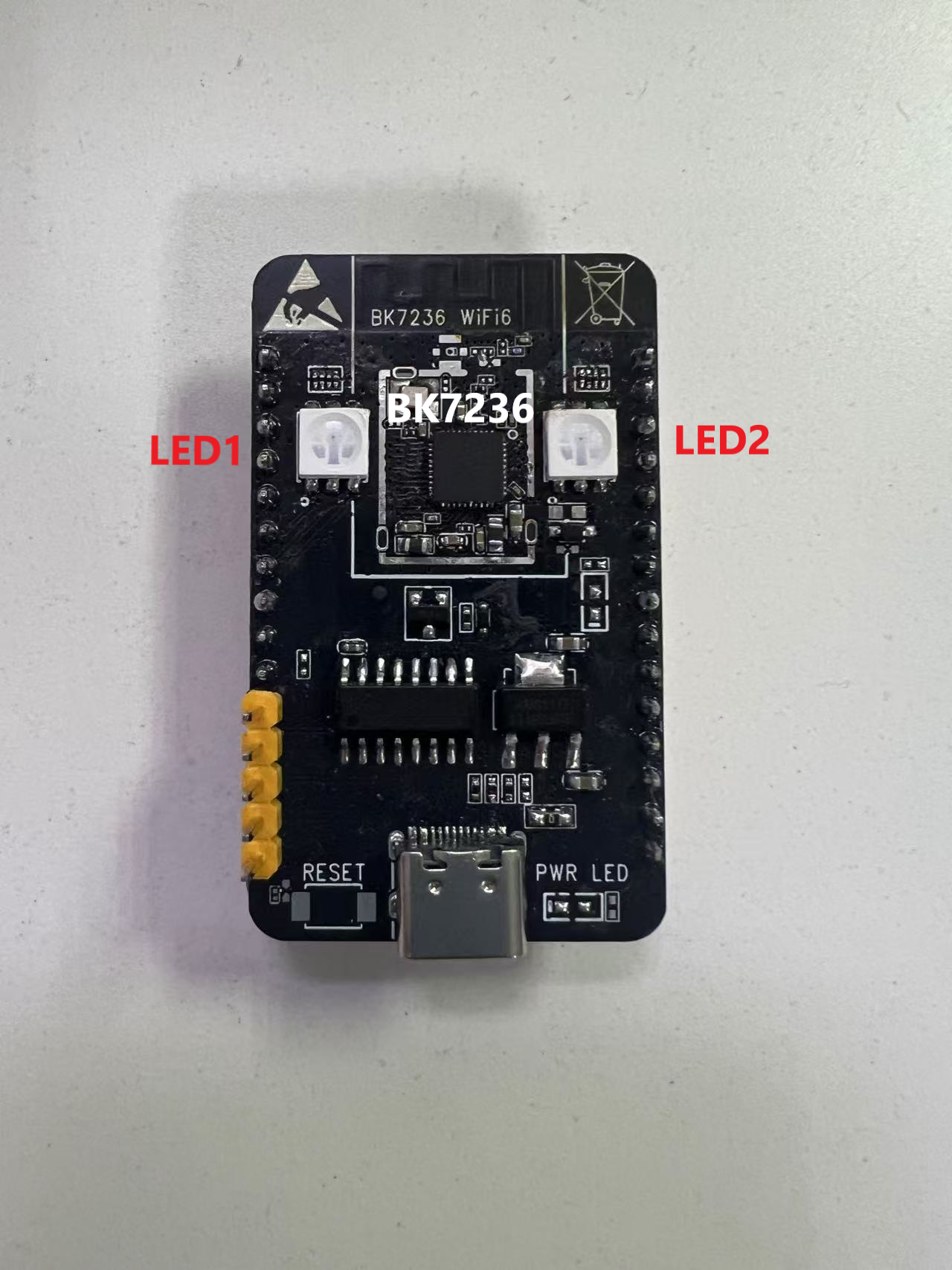
bk7236模组
在这个模组中,左侧的LED1与PWM1寄存器控制的GPIO引脚相连,因此,LED1支持PWM功能。
支持PWM的三色LED灯的软件配置
支持PWM的三色LED灯的软件运行逻辑与普通的三色灯逻辑相同,如果您没有阅读三色LED灯的软件设计逻辑,请详见:普通三色LED灯的软硬件机制和接口介绍 下面介绍的是PWM独有的部分,将以上图中的7236模组为基础,对PWM功能进行简单的介绍。
PWM在LED三色灯上的相关介绍
PWM(脉冲宽度调制)是一种常用的模拟信号处理技术,它通过控制脉冲信号的宽度来模拟不同强度的模拟信号。在LED(发光二极管)应用中,PWM主要用于调节LED的亮度。
以下是PWM在LED上的主要用途:
亮度调节 :通过改变PWM的占空比(脉冲高电平的时间与整个周期时间的比例),可以控制LED的亮度。占空比越高,LED的亮度就越高;占空比越低,LED的亮度就越低。
模拟亮度 :虽然LED是数字设备,但通过PWM可以实现类似模拟调节亮度的效果。通过改变PWM的频率和占空比,可以产生不同亮度的连续变化。
消除闪烁 :LED在低亮度时可能会出现闪烁,这会让人感到不适。通过使用适当频率的PWM(通常在几千赫兹以上),可以有效地消除这种闪烁。
色彩控制 :在RGB LED(红色、绿色、蓝色发光二极管)应用中,PWM可以分别控制每个颜色的亮度,从而实现混合色光的调节。
图像显示 :在一些特殊的LED应用中,如LED显示屏,PWM可以用来控制每个像素的亮度,实现动态图像的显示。
总之,PWM在LED中的应用非常广泛,是现代电子设备中调节LED亮度和颜色的一种重要技术。
PWM在bk7236上的相关实现
bk7236上面的PWM相关介绍请参见:
对此,我们将使用如下的pwm channel:
颜色引脚 |
pwm channel |
|---|---|
BK_MESH_PWM_RED_PIN |
8 |
BK_MESH_PWM_GREEN_PIN |
6 |
BK_MESH_PWM_BLUE_PIN |
10 |
备注
请根据自己的实际硬件更改!
可以将pwm channel在本工程理解为对应的GPIO引脚,只不过在PWM项目上调用的函数不同而已!
PWM LED实现
demo路径:
components/demos/bk_mesh_led_demo_v2.c
备注
PWM项目与之前的LED项目不适用相同工程,若使用PWM项目,请使用如下编译命令:
make bk7236 -j8 PROJECT=bk_mesh/pwm_led
demo工程上使用的内部API
在demo工程中,使用了一些IDK内部的PWM的API,这些API的介绍如下:
bk_mesh_led_demo_pwm_api.h
- bk_mesh_led_demo_pwm_api.h路径:
components/demos/inc
demo工程上使用的对外API
与普通LED三色灯软件设计相同,PWM工程同样需要注册对外的API,对外API接口如下:
bk_mesh_led_demo_v2.h
- bk_mesh_led_demo_v2.h路径:
components/demos/inc
备注
这几个函数的具体实现可以由客户自行实现,也可以使用demo中已经写好的函数实现。
这几个函数只是PWM LED内部的具体设置实现,下面我们要做的就是将这些API统一到对应的vendor API上。
与LED三色灯工程一样,所有的vendor信息都存储在 g_vendor_info 这个全局结构体下,而在PWM项目上,我们需要关注的则是 struct bk_mesh_256_color_light_msg led_256_control
结构体struct bk_mesh_256_color_light_msg的定义如下:
bk_mesh_led_demo_pwm.h
- bk_mesh_led_demo_pwm.h路径:
components/demos/inc
每个成员的解释如下:
变量
类型 | 说明
type_msg
u8
上一次配置的消息类型,在inform函数中使用
layer
u8
上一次配置的层级信息,在inform函数中使用
time
u16
上一次配置的闪烁时间
bitmap
u16[3]
上一次配置的RGB值,其中从低到高为R,G,B(中间暂存,不代表最后的配置值)
red_config
pwm_period_duty_config_t
上一次配置的R值,还包括周期数和占空比
green_config
pwm_period_duty_config_t
上一次配置的G值,还包括周期数和占空比
blue_config
pwm_period_duty_config_t
上一次配置的B值,还包括周期数和占空比
对于pwm_period_duty_config_t的解释,请参见如下网址:
此外,为了表征编译的版本支持PWM项目,需要在初始化函数中执行下列操作:
g_vendor_info.vendor_bitmap |= BK_MESH_DEMO_SUPPORT_PWM_LED;
其中, BK_MESH_DEMO_SUPPORT_PWM_LED 占用Bitmap中的BIT2,目前为内部消息机制使用,用户如需在外部APP中设置,请参见TODO 开发者文档!
备注
使用PWM工程需要开启CONFIG_BK_WIFI_MESH_DEMO_PWM_LED,并且需要注意的是,只有LED1支持PWM,而LED2只支持单一颜色的配置。 而在使用双LED的bk7236硬件模组情况下,不需要开启CONFIG_BK_WIFI_MESH_DEMO_LED,这个宏是为了单一LED灯硬件组准备的。
demo工程上使用的对外API的注册
与LED三色灯工程相同,上面提到的PWM LED工程使用到的对外的API也是在vendor统一对外的API中使用, 整体通过以 g_vendor_info.vendor_bitmap 存储的内部bit值和 Vendor API 所携带的外部bit值进行比较而判断执行哪个工程(当然也有对应宏的保护) 下图为PWM工程的Vendor API内部的执行流程图:
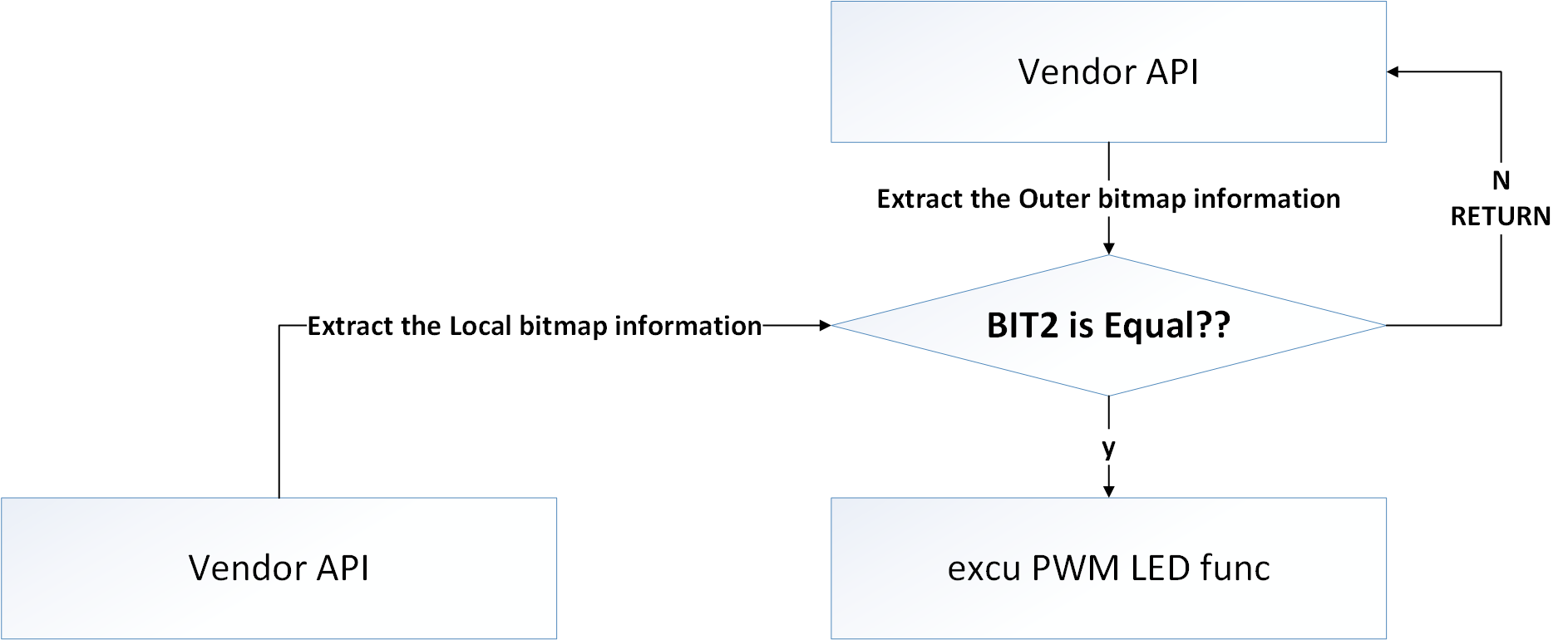
Vendor API flow for PWM
备注
set vendor函数目前在SDK内部有支持,但是Beken给出的手机APP侧目前不支持配置,因此默认SDK不支持PWM LED的配置!
如有必要可自行实现APP侧设置或联系开发者!
demo工程上使用的外部消息区域的Vendor字段格式
PWM LED工程使用外部消息区域的Vendor字段格式与三色LED工程相同,只是区别如下:
- PWM LED工程使用bitmap中的BIT2作为标记
PWM LED工程使用bitmap2 Content字段
下面介绍一下PWM LED工程相关Vendor字段格式
Bitmap2
Bitmap0目前被PWM LED工程所用,用户的外部设备和节点之间通信,如涉及到PWM LED交互,则需要将此bit置1。
当该bit为1时代表本命令支持PWM LED控制
当该bit为0时代表本命令不支持PWM LED控制
备注
本字段在 CONFIG_BK_WIFI_MESH_DEMO_PWM_LED 配置为true的情况下生效!
Bitmap2 Content
备注
本字段在 CONFIG_BK_WIFI_MESH_DEMO_PWM_LED 配置为true的情况下生效!
Bitmap0 Content的结构如下:
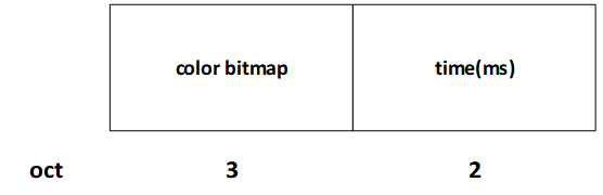
PWM Bitmap2 COntent
下面介绍一下Bitmap2 Content里面各个字段的含义:
color bitmap:想要配置或者查询的颜色,在PWM LED工程下,采用RGB各占一个字节的模式,因此长度为3个字节,因此本字段格式如下:

pwm color bitmap
time:想要配置或者查询的颜色闪烁时间
该字段配置闪烁时间,单位为毫秒。当此值非0时,默认LED灯闪烁。
内部状态设置机制
下表是目前使用到的内部消息:
枚举
事件说明
NODE_POWER_ON
节点开机
NODE_START_NET
开始组网
NODE_NET_FAIL
组网失败
NODE_NET_LAYER
根据层级配置颜色,SDK默认,颜色见下表
NODE_BREAKDOWN
节点失效
NODE_REVOVER
节点恢复
NODE_LAYER_CHANGE
节点层级更改
NODE_STOP
节点停止
目前SDK默认的层级-颜色对照表:
层级
颜色
1
red
2
green
3
blue
4
yellow
5
magenta
6
cyan
特殊事件颜色:
事件
颜色
NODE_POWER_ON
white
NODE_BREAKDOWN
当前颜色闪烁
NODE_STOP
white