GPIO User Guide
Beken chip supports abundant GPIO pins, some GPIOs can’t be used by the application:
In most Beken chips, UART0 is enabled by default and GPIO 10 and GPIO 11 are used by UART0.
Some GPIOs may be used by specific peripheral device, the application can’t use the GPIOs used by that device if the device is enabled by software. E.g. in BK7236, the SPI-1 can use GPIO 2/3/4/5, the application can’t use GPIO 2/3/4/5 if SPI-1 is enabled by the software, the application can still use GPIO 2/3/4/5 if the SPI-1 is disabled by software.
If the GPIOs are already used by the periperal devices, the GPIO API, such as cpp:func:bk_gpio_set_config will return GPIO_ERR_INTERNAL_USED.
Generally speaking, the GPIO user can take following steps to use the GPIO:
Read the chip hardware datasheet to gain overview about how the peripheral use the GPIOs
Check the enabled peripheral device in your application and find out the GPIOs used by the devices
Always check the return value of GPIO API, make sure it’s not GPIO_ERR_INTERNAL_USED
Note
The GPIO implements time-division multiplexing. At the same time, it can only serve sa an ordinary GPIO or use its second function.
GPIO MAP Config
gpio_map.h
The BK7258 features a multi-core AMP architecture. GPIO is configured according to the MAP(GPIO_DEFAULT_DEV_CONFIG) during driver initialization of each CPU core. Each row in the map contains nine elements. The 9 elements are as follows:
gpio_id:Corresponding PIN number starting from 0
second_func_en:Whether to enable the secondary function.
second_func_dev:Select the second function of the PIN.(Currently, a single GPIO PIN can reuse up to eight secondary functions. see GPIO_DEV_MAP. This table cannont be modified bu user)
io_mode:Select the IO operating mode, input\output\high resistance.(In output mode,it is an open-drain output)
pull_mode:Select IO level pull up or pull down
int_en:Whether to turn on interrupt
int_type:Select trigger interrupt condition, high\low\rise\fall.
low_power_io_ctrl:Low power whether to maintain the output level(Configuring GPIO_LOW_POWER_KEEP_INPUT_STATUS can set the GPIO as a wake-up source. If it is set as a wake-up source, you need to enable the interrupt and configure the interrupt type. If this bit is not set, the GPIO will be in high resistance when entering low power mode).
driver_capacity:Driver ability selection, a total of four levels.
GPIO partial usage introduction:
Customers need to configure the GPIO_DEFAULT_DEV_CONFIG table according to their board configuration requirements.You can freely configure the GPIO_DEFAULT_DEV_CONFIG table according to the capabilities of each GPIO defined in the GPIO_DEV_MAP table. If you want to change the function of a GPIO while the program is running, you can use the gpio_dev_unmap() function to cancel the original mapping, and then use the gpio_dev_map() function to perform a new mapping. When initializing GPIO peripherals in the gpio_hal.c file, the gpio_hal_default_map_init() function initializes GPIO according to the GPIO_DEFAULT_DEV_CONFIG table during the first initialization (only if the macro CONFIG_GPIO_DEFAULT_SET_SUPPORT is enabled). If this macro is not enabled, the platform will not operate the GPIO, and the default state of GPIO will be set to a high resistance.
Currently, the BK7258 adopts a basic AMP architecture, which may cause GPIO interrupts to be handled bu multiple CPU cores, affecting the program’s expected behavior(Because CPU1 has a higher clock speed than CPU0, this may lead to interrupt loss). To resovle this issue, the following measures are proposed:
By following the third point, a custom GPIO map table can be defined for each CPU core, with different GPIOs assigned to different cores. This way, each CPU core will only respond to interrupts in its corresponding map table, preventing multiple cores from handling the same interrupt, and ensures that the program behaves as expected.
(Note: After creating a new project, each CPU must configure the GPIOs it needs to control to ensure that each CPU manages its own GPIOs, registers the corresponding interrupt callback functions, and ensures the program runs as expected.)
override the default GPIO_DEFAULT_DEV_CONFIG in a customized way, follow the steps below:
Open macro definition: Open the CONFIG_USR_GPIO_CFG_EN macro in your project configuration file to enable the custom GPIO configuration function.
Create the usr_gpio_cfg.h file: Create the usr_gpio_cfg.h header file in an appropriate location in your project and define your custom GPIO_DEFAULT_DEV_CONFIG in this file. This configuration should contain the initialization settings and mappings for all GPIOs you want. For example, You can add usr_gpio_cfg.h header file to the ‘bk_avdk_release\projects\lvgl\86box\config\bk7258’.
It should be noted that the newly mapped function must have been defined in the GPIO_DEV_MAP table. During initialization, the chip will configure the GPIO status according to the GPIO_DEFAULT_DEV_CONFIG table.(note:Make sure to include the usr_gpio_cfg.h file in your code so that your custom GPIO configuration is used when compiling.)
Low power state: Can be configured as input mode and output mode. If the corresponding GPIO (GPIO_LOW_POWER_DISCARD_IO_STATUS) is not used during low power , the low power mode program will set the GPIO to a high resistance state to prevent leakage during low power mode.
maintain the output state of GPIO in low-power mode, there are two methods to configure:
Configure the GPIO_DEFAULT_DEV_CONFIG table according to the instructions.
Use the bk_gpio_register_lowpower_keep_status() function to register. The default number is 4, which can be modified using CONFIG_GPIO_DYNAMIC_KEEP_STATUS_MAX_CNT.
Use the bk_gpio_unregister_lowpower_keep_status() function to cancel the registration of GPIOs that need to maintain their status.
When entering low-power mode, multiple external GPIOs can be set as wake-up sources. If any of these GPIOs generates an interrupt signal, the chip can wake up from low-power mode. There are currently three methods to configure wake-up sources:
Configure according to the instructions in the GPIO_DEFAULT_DEV_CONFIG table.
Set multiple wake-up sources in the GPIO_STATIC_WAKEUP_SOURCE_MAP.
Register wake-up sources using the bk_gpio_register_wakeup_source() function. (The default number is 4, but it can be modified using CONFIG_GPIO_DYNAMIC_WAKEUP_SOURCE_MAX_CNT).
Use the bk_gpio_unregister_wakeup_source() function to cancel the registration of wake-up sources.
When entering low power mode(Low voltage only), the status of GPIO will be backed up. After exiting, GPIO will be automatically restored to the state before entering low power mode. (note:After exiting from deep sleep mode, it is equivalent to a soft restart, and the GPIO status will not be automatically restored.If necessary to exit from deep sleep mode and maintain the GPIO status, see point 8.)
To maintain GPIO states during OTA (Over-The-Air) updates or software restarts:
Initialize the GPIO driver without power loss by adding code to skip GPIOs that need to maintain their output state. Modify the file gpio_hal.c around line 335. For example, to keep GPIO20 in output mode, add: if(default_map[i].gpio_id == GPIO_20) continue;
9. When setting up input interrupt detection, it is essential to ensure the signal level is stable before enabling the interrupt. The handling logic is as follows: first, clamp the signal level to either a high level or a low level (depending on the interrupt trigger mode). For instance, if the interrupt is triggered by a rising edge, the GPIO should be initially set to a low state to prevent jitter or random high resistance values from causing unintended triggers. 10. GPIOs can be configured for their secondary functions in two ways: statically and dynamically.
Static Configuration: In the GPIO_DEFAULT_DEV_CONFIG table, you set the second_func_en and second_func_dev members. Once these settings are enabled, the GPIOs will automatically be initialized to their secondary functions during the chip’s power-on sequence.
Dynamic Configuration: This is achieved by calling the gpio_dev_map() or gpio_dev_unprotect_map() functions. Notably, gpio_dev_unprotect_map() does not check if the GPIO is already in use by another CPU core, which could lead to unintended behavior. In contrast, gpio_dev_map() incorporates a locking mechanism during the reconfiguration process, ensuring atomic operations and preventing conflicts by guaranteeing that only one operation can execute at a time.
(Note: To prevent conflicts where a single pin is used by multiple functions, it is recommended that all GPIO pins be configured by GPIO_DEFAULT_DEV_CONFIG table. Only in special cases, such as time-division multiplexing scenarios, should dynamic configuration of GPIO be used.)
Note
usr_gpio_cfg.h must be configured.
- The driving capacity of GPIO is shown in the table below. REG indicates the set value of the GPIO register, there are four levels for drive capability.
REG=2
REG=102
REG=202
REG=302
P14
10.49
19.95
33.72
40.8
P15
10.48
19.9
33.28
40.03
P16
10.41
19.65
32.76
39.35
P17
10.36
19.45
32.26
38.6
High level pull current(mA)
REG=0
REG=100
REG=200
REG=300
P14
8.54
16.09
26.05
32
P15
8.56
16.19
26.47
32.6
P16
8.56
16.35
26.87
33.24
P17
8.62
16.5
27.24
33.85
Low level-sink current(mA)
Example:
- Configure GPIO_0 to function [GPIO_DEV_I2C1_SCL] and GPIO_1 to function [GPIO_DEV_I2C1_SDA]:
gpio_id
second_func_en
second_func_dev
io_mode
pull_mode
int_en
int_type
low_power_io_ctrl
driver_capacity
GPIO_0
GPIO_SECOND_FUNC_ENABLE
GPIO_DEV_I2C1_SCL
GPIO_IO_DISABLE
GPIO_PULL_UP_EN
GPIO_INT_DISABLE
GPIO_INT_TYPE_LOW_LEVEL
GPIO_LOW_POWER_DISCARD_IO_STATUS
GPIO_DRIVER_CAPACITY_3
GPIO_1
GPIO_SECOND_FUNC_ENABLE
GPIO_DEV_I2C1_SDA
GPIO_IO_DISABLE
GPIO_PULL_UP_EN
GPIO_INT_DISABLE
GPIO_INT_TYPE_LOW_LEVEL
GPIO_LOW_POWER_DISCARD_IO_STATUS
GPIO_DRIVER_CAPACITY_3
PS:GPIO is turned off by default when the second function is used (io_mode is [GPIO_IO_DISABLE]). I2C needs more driving capability (driver_capacity is [GPIO_DRIVER_CAPACITY_3]).
- GPIO_0 is set to high resistance(Default state):
gpio_id
second_func_en
second_func_dev
io_mode
pull_mode
int_en
int_type
low_power_io_ctrl
driver_capacity
GPIO_0
GPIO_SECOND_FUNC_DISABLE
GPIO_DEV_INVALID
GPIO_IO_DISABLE
GPIO_PULL_DISABLE
GPIO_INT_DISABLE
GPIO_INT_TYPE_LOW_LEVEL
GPIO_LOW_POWER_DISCARD_IO_STATUS
GPIO_DRIVER_CAPACITY_0
PS:Disable all config
- GPIO_0 is set to input key and falling edge to trigger the interrupt:
gpio_id
second_func_en
second_func_dev
io_mode
pull_mode
int_en
int_type
low_power_io_ctrl
driver_capacity
GPIO_0
GPIO_SECOND_FUNC_DISABLE
GPIO_DEV_INVALID
GPIO_INPUT_ENABLE
GPIO_PULL_UP_EN
GPIO_INT_ENABLE
GPIO_INT_TYPE_FALLING_EDGE
GPIO_LOW_POWER_DISCARD_IO_STATUS
GPIO_DRIVER_CAPACITY_0
PS:Turn off the second function related. There are 4 interrupt trigger conditions:[GPIO_INT_TYPE_LOW_LEVEL],[GPIO_INT_TYPE_HIGH_LEVEL],[GPIO_INT_TYPE_RISING_EDGE],[GPIO_INT_TYPE_FALLING_EDGE].
- GPIO_0 acts as a low power wake-up source, Falling edge wake-up:
gpio_id
second_func_en
second_func_dev
io_mode
pull_mode
int_en
int_type
low_power_io_ctrl
driver_capacity
GPIO_0
GPIO_SECOND_FUNC_DISABLE
GPIO_DEV_INVALID
GPIO_INPUT_ENABLE
GPIO_PULL_UP_EN
GPIO_INT_ENABLE
GPIO_INT_TYPE_FALLING_EDGE
GPIO_LOW_POWER_KEEP_INPUT_STATUS
GPIO_DRIVER_CAPACITY_0
PS:low_power_io_ctrl is [GPIO_LOW_POWER_KEEP_INPUT_STATUS].
Q&A
In low-power mode, both the RTC and GPIO interrupts are configured. However, after the RTC triggers, the GPIO functionality becomes ineffective.
This issue arises because, before entering low-power mode, the MCU backs up the states of the GPIOs. To prevent the MCU from failing to wake up due to the lack of enabled wake-up GPIO pin interrupts, the wake-up GPIO pin interrupts are enabled in low-power mode. Upon exiting the interrupt, the state of that pin is restored to what it was before entering low-power mode. If the wake-up pin interrupt was not enabled before entering low-power mode, it remains disabled after exiting low-power mode. Consequently, the wake-up GPIO interrupt cannot be triggered in normal operating mode.
After entering deep sleep mode, tapping on the UART can wake up the device.
Because of the needs of some secondarios,the default supports for using the UART to wake up the device, if you don’t need this function, You can comment out GPIO_10 in the GPIO_STATIC_WAKEUP_SOURCE_MAP section of the gpio_map.h file.
Coordination issues between multi-core operations and the same GPIO, A customer in a multi-core AMP system did not adopt a CPU-independent GPIO configuration scheme, resulting in the following typical issues, manifested as:
After enabling the DVP camera, the key interrupt is occasionally lost.
When only LCD or UVC is enabled, the key GPIO interrupt does not trigger approximately 50% of the time.
The AMP architecture of BK7258 features multiple CPUs sharing hardware resources. All GPIO pins share a common GPIO interrupt line. If each CPU does not configure its own required GPIO, an interrupt on any GPIO pin will trigger all CPUs to receive the interrupt notification and execute the interrupt handling function.Enabling peripherals such as DVP and LCD can start up CPU1, which operates at a higher frequency than CPU0. This higher frequency might inadvertently clear interrupt flag bits, leading to lost GPIO interrupts on CPU0. To prevent this, it is essential that each CPU configures its own GPIO map table individually.
GPIO API Status
API |
BK7258 |
BK7258_cp1 |
|---|---|---|
Y |
Y |
|
Y |
Y |
|
Y |
Y |
|
Y |
Y |
|
Y |
Y |
|
Y |
Y |
|
Y |
Y |
|
Y |
Y |
|
Y |
Y |
|
Y |
Y |
|
Y |
Y |
|
Y |
Y |
|
Y |
Y |
|
Y |
Y |
|
Y |
Y |
|
Y |
Y |
|
Y |
Y |
|
Y |
Y |
Application Example
- DEMO1:
GPIO_0 as wake-up source for DeepSleep or LowPower, pseudo code description and interpretation.
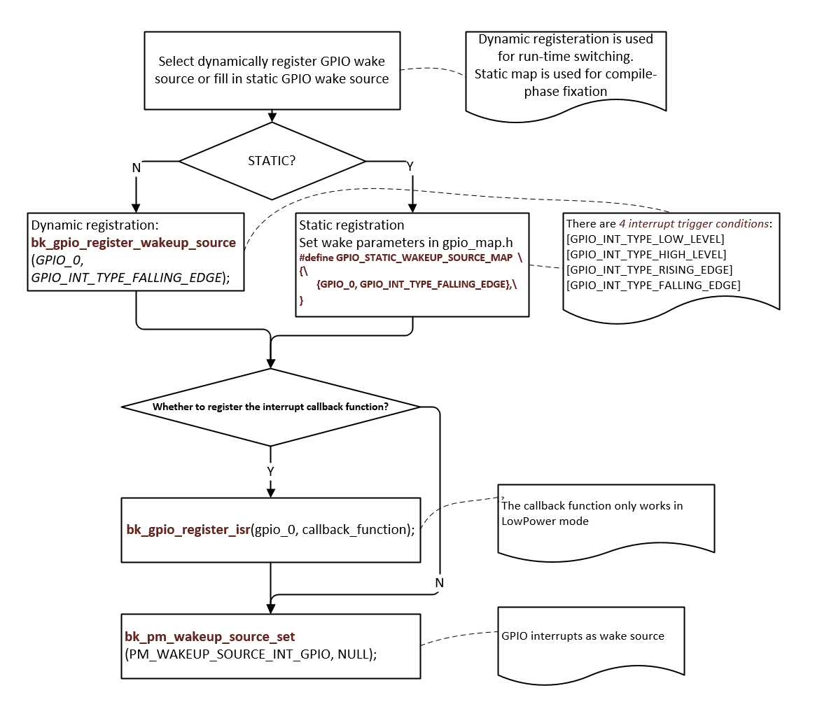
Figure 1. GPIO as wake-up source for DeepSleep or LowPower
GPIO API Reference
Header File
Functions
-
bk_err_t bk_gpio_driver_init(void)
Init the GPIO driver.
This API init the resoure common to all GPIO channels:
Init GPIO driver control memory
This API should be called before any other GPIO APIs.
- Returns
BK_OK: succeed
others: other errors.
-
bk_err_t bk_gpio_driver_deinit(void)
Deinit the GPIO driver.
This API free all resource related to GPIO and power down all GPIO channels.
- Returns
BK_OK: succeed
others: other errors.
-
void bk_gpio_set_value(gpio_id_t id, uint32_t v)
Direct set GPIO config value.
@NOTES Please be care to use this API,unless you know the detail mean, because it will set the GPIO config value. Sometimes the special GPIO needs to re-used by one more owner, after the second owner re-used it, it should restore the config value. Before re-use a GPIO, the owner can call bk_gpio_get_value and bakup it, after re-used finish, it call bk_gpio_set_value to restore the prevous value.
-
uint32_t bk_gpio_get_value(gpio_id_t id)
get GPIO config value.
-
bk_err_t bk_gpio_enable_output(gpio_id_t gpio_id)
enable GPIO output mode
- Returns
BK_OK: succeed
BK_ERR_GPIO_CHAN_ID: invalid GPIO channel
others: other errors.
-
bk_err_t bk_gpio_disable_output(gpio_id_t gpio_id)
disable GPIO output mode
- Returns
BK_OK: succeed
BK_ERR_GPIO_CHAN_ID: invalid GPIO channel
others: other errors.
-
bk_err_t bk_gpio_enable_input(gpio_id_t gpio_id)
enable GPIO input mode
- Returns
BK_OK: succeed
BK_ERR_GPIO_CHAN_ID: invalid GPIO channel
others: other errors.
-
bk_err_t bk_gpio_disable_input(gpio_id_t gpio_id)
disable GPIO input mode
- Returns
BK_OK: succeed
BK_ERR_GPIO_CHAN_ID: invalid GPIO channel
others: other errors.
-
bk_err_t bk_gpio_enable_pull(gpio_id_t gpio_id)
enable GPIO pull mode
- Returns
BK_OK: succeed
BK_ERR_GPIO_CHAN_ID: invalid GPIO channel
others: other errors.
-
bk_err_t bk_gpio_disable_pull(gpio_id_t gpio_id)
disable gpio pull mode
- Returns
BK_OK: succeed
BK_ERR_GPIO_CHAN_ID: invalid GPIO channel
others: other errors.
-
bk_err_t bk_gpio_pull_up(gpio_id_t gpio_id)
set GPIO as pull up mode
- Returns
BK_OK: succeed
BK_ERR_GPIO_CHAN_ID: invalid GPIO channel
others: other errors.
-
bk_err_t bk_gpio_pull_down(gpio_id_t gpio_id)
set GPIO as pull down mode
- Returns
BK_OK: succeed
BK_ERR_GPIO_CHAN_ID: invalid GPIO channel
others: other errors.
-
bk_err_t bk_gpio_set_config(gpio_id_t gpio_id, const gpio_config_t *config)
Config the GPIO mode.
This API config GPIO’s mode
BK_OK: succeed
BK_ERR_GPIO_CHAN_ID: invalid GPIO channel
BK_ERR_GPIO_INVALID_MODE: invalid GPIO’s io_mode/pull_mode
BK_ERR_GPIO_INTERNAL_USED:GPIO was map to another device
others: other errors.
-
bk_err_t bk_gpio_set_output_high(gpio_id_t gpio_id)
Set the GPIO output high,.
- Returns
BK_OK: succeed
BK_ERR_GPIO_CHAN_ID: invalid GPIO channel
BK_ERR_GPIO_NOT_OUTPUT_MODE:GPIO not in output mode
others: other errors.
-
bk_err_t bk_gpio_set_output_low(gpio_id_t gpio_id)
Set the GPIO output low,.
- Returns
BK_OK: succeed
BK_ERR_GPIO_CHAN_ID: invalid GPIO channel
BK_ERR_GPIO_NOT_OUTPUT_MODE:GPIO not in output mode
others: other errors.
-
bool bk_gpio_get_input(gpio_id_t gpio_id)
Get the GPIO input value,.
This API get GPIO’s input level: 0 :low_level 1:high_level.
- Returns
input value
BK_ERR_GPIO_CHAN_ID: invalid GPIO channel
BK_ERR_GPIO_NOT_INPUT_MODE : GPIO is not input mode
others: other errors.
-
bool bk_gpio_set_capacity(gpio_id_t gpio_id, uint32 capacity)
Set the GPIO driver capacity.
This API Set GPIO’s output driver capacity which range is 0~3.
- Returns
input value
BK_ERR_GPIO_CHAN_ID: invalid GPIO channel
BK_ERR_GPIO_NOT_INPUT_MODE : GPIO is not input mode
others: other errors.
-
bk_err_t bk_gpio_set_interrupt_type(gpio_id_t gpio_id, gpio_int_type_t type)
Config the GPIO intterrupt type mode when use gpio intterrupt mode,.
This API config all GPIO channels’ intterrupt mode, the mode included in gpio_int_type_t.
- Returns
BK_OK: succeed
BK_ERR_GPIO_CHAN_ID: invalid GPIO channel
BK_ERR_GPIO_INVALID_INT_TYPE: invalid GPIO int type
others: other errors.
-
bk_err_t bk_gpio_enable_interrupt(gpio_id_t id)
Enable GPIO intterrupt.
- Returns
BK_OK: succeed
BK_ERR_GPIO_CHAN_ID: invalid GPIO channel
BK_ERR_GPIO_NOT_INPUT_MODE : GPIO is not input mode
others: other errors.
-
bk_err_t bk_gpio_disable_interrupt(gpio_id_t id)
Disable GPIO intterrupt.
- Returns
BK_OK: succeed
BK_ERR_GPIO_CHAN_ID: invalid GPIO channel
others: other errors.
-
bk_err_t bk_gpio_clear_interrupt(gpio_id_t gpio_id)
Clear GPIO intterrupt.
- Returns
BK_OK: succeed
BK_ERR_GPIO_CHAN_ID: invalid gpio channel
others: other errors.
-
bk_err_t bk_gpio_register_isr(gpio_id_t id, gpio_isr_t isr)
Register the interrupt service routine for GPIO channel.
This API regist gpio isr callback function.
- Returns
BK_OK: succeed
BK_ERR_GPIO_CHAN_ID: invalid gpio channel
others: other errors.
-
bk_err_t bk_gpio_unregister_isr(gpio_id_t id)
Unregister the interrupt service routine for GPIO channel.
This API deregist gpio isr callback function.
- Returns
BK_OK: succeed
BK_ERR_GPIO_CHAN_ID: invalid gpio channel
others: other errors.
-
bk_err_t bk_gpio_reg_save(uint32_t *gpio_cfg)
Register save all gpio reg value.
This API save all gpio reg value function.
- Returns
BK_OK: succeed
others: other errors.
-
bk_err_t bk_gpio_reg_restore(uint32_t *gpio_cfg)
Register restore all gpio reg value.
This API restore all gpio reg value function.
- Returns
BK_OK: succeed
others: other errors.
GPIO API Typedefs
Header File
Structures
-
struct gpio_wakeup_config_t
Macros
-
BK_ERR_GPIO_CHAN_ID
gpio channel number is invalid
-
BK_ERR_GPIO_INVALID_MODE
gpio mode is invalid
-
BK_ERR_GPIO_NOT_INPUT_MODE
gpio is not in input mode
-
BK_ERR_GPIO_SET_INVALID_FUNC_MODE
gpio perial mode is invalid or was be set as 2nd func
-
BK_ERR_GPIO_INVALID_INT_TYPE
gpio int type is invalid
-
BK_ERR_GPIOS_MAP_NONE
gpio map device is none
-
BK_ERR_GPIO_NOT_OUTPUT_MODE
gpio is not in output mode
-
BK_ERR_GPIO_BITS_NUM
gpio map bit num is error
-
BK_ERR_GPIO_INTERNAL_USED
gpio map was be map to a device
-
BK_ERR_GPIO_MAP_PWMS_CHAN
gpio map to pwm pwms’ channel is invalid
-
BK_ERR_GPIO_INVALID_ID
gpio id is invalid
-
BK_ERR_GPIO_WAKESOURCE_OVER_MAX_CNT
too much GPIO is register to wakeup source
-
BK_ERR_ANA_GPIO_TYPE_NOT_SUPPORT
analog gpio wake source pin config is invalid>
Type Definitions
-
typedef void (*gpio_isr_t)(gpio_id_t gpio_id)
GPIO interrupt service routine.