SPI User Guide
Summary
SPI (Serial Peripheral Interface) It is a high-speed, full duplex, synchronous communication bus, which is widely used in the communication between ADC, Flash and MCU.
SPI Connection
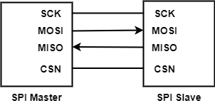
The above figure shows SPI hardware connection, where:
SCK: Clock signal, which provides the clock for data transmission to synchronize data transmission.
MOSI:Master Output, Slave Input
MISO:Master Input, Slave Output
CSN: The master selects the corresponding slave to transmit data, which is valid at low level
Beken chip usually has 1 SPI controller, and BK7236 supports two SPI (SPI1, SPI2).
SPI Mode
SPI There are four communication modes, and their differences mainly depend on the polarity and phase of SPI clock.
SPI Mode |
CPOL |
CPHA |
SCK Initial level |
Sampling clock edge |
|---|---|---|---|---|
0 |
0 |
0 |
LOW |
First |
1 |
0 |
1 |
LOW |
Second |
2 |
1 |
0 |
HIGH |
First |
3 |
1 |
1 |
HIGH |
Second |
Mode 0 and mode 3 are commonly used because they both sample data on the rising edge. It doesn’t matter what the initial level of the clock is, just collect data on the rising edge. Beken SPI Four modes of SPI are supported, and clock polarity and phase can be set through ‘bk_spi_set_mode()’
SPI Sequential
SPI Timing
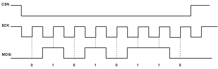
The above figure shows the timing chart of master transmitting data(0x56(0b0101 0110) to slave(CPOL = 1, CPHA = 1,MSB first).
CS low level, select the corresponding slave
In each SCK clock cycle, the MOSI outputs the corresponding level, and first outputs the high bit of data
Slave will read the level on the MOSI at the rising edge of each clock cycle
The Beken SPI data frame length can be set to 8 bit or 16 bit, which can be set through ‘bk_spi_set_bit_width()’ SPI can be set to MSB first or LSB first, which can be set through ‘bk_spi_set_bit_order()’.