DMA User Guide
Summary
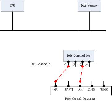
DMA Transmission copies data from one address space to another address space, providing high-speed data transmission between peripherals and memory or between memory and memory. A typical DMA implementation is usually shown in the figure below.
DMA Overview
Note
The actual DMA architecture implementation may be different from the above figure, which is an abstract overview for easy understanding.
CPU, DMA controller and DMA memory are connected through bus. A DMA controller can support multiple channels, and different channels can transmit simultaneously. Before data transmission between peripheral and memory, you need to select a channel and configure the corresponding parameters.
BK7236 supports 2 DMA The controller and each controller 8 DMA channels. Although the six channels can work at the same time, there is only one bus, so there is actually only one channel that can transmit data on the bus at a specific time. When multiple different DMA channels have data transmission at the same time, DMA schedules the channels. DMA channel has two scheduling modes:
Poll scheduling, all channels have the same priority, and request scheduling first
Based on priority scheduling, the scheduling method and priority can be set through A.:cpp:func:bk_dma_init
DMA Configuration
For DMA transmission, the following configurations are usually required:
Configure source and destination devices
Set the data width of source and destination devices
Set data volume
Transmission times (single transmission or cyclic transmission)
DMA Transfer Times Setting
DMA The number of transfers can be set through the transfer mode. DMA has two transfer modes:
SINGLE Mode
REPEAT Mode
Single Mode
The single mode is shown in the figure below. The transfer from ‘start’ to ‘’start’+’len’’ ends. Generally, len is set to ‘’end’-‘start’’, that is, the length of the whole block.
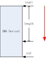
DMA Single Mode
Cycle Mode
The loop mode is shown in the figure below. After DMA is transferred from start to end, it will be transferred from start to end again, and it will be repeated until DMA is stopped. When the SRC or DST device has a single address, the address pointed to by Start is transmitted each time in Repeat mode until the DMA is stopped.
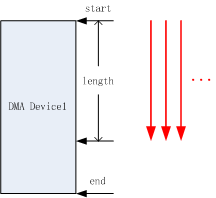
DMA Repeat Mode
DMA Transmission Scenario
DMA Basic principles of address configuration:
If the address to be transmitted is a single address, that is, if the available address length of the device address is equal to the data width during DMA transmission, you only need to configure the start address and the end address as 0. For example, if the bit width of the UART device is 8 bits, only these 8 bits are used for DMA transmission each time, so you only need to configure the start address as the UART FIFO address and the end as 0
If the address to be transmitted is a block address, that is, the address length exceeds the data width, Start is configured as the starting address of the block address and End is configured as the ending address of the block address
Specific applications can be divided into the following three scenarios:
Single address to single address transmission
Single address to block address transfer
Block address to block address transfer
Single address to single address transmission
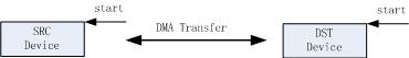
DMA case1
As shown in the figure above, SRC/DST devices only need to configure the start address, and the end is 0
Single address to block address transfer
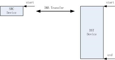
DMA case2
As shown in the figure above, SRC devices only need to configure the start address, end is 0, and end devices need to configure the start/end address.
Block address to block address transfer
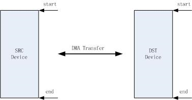
DMA case3
As shown in the figure above, SRC devices only need to configure the start address, end is 0, and end devices need to configure the start/end address.