SARADC
- link_to_translation
zh_CN:[中文]
Summary
SARADC currently supports up to 16 channels. In BK7236, channels 1-6, 10, and 12-15 are digital channels, and the rest are analog channels. The SARADC accuracy defaults to 13bit. The general accuracy is not dynamically adjusted in SARADC driver.
SARADC Mode Type:
Sleep Mode:
ADC stops any operation in the sleep mode, which is equivalent to the ‘Power Down’ state
Single Step Mode:
In the single step mode, ADC will only collect one data at a time. After the collection, it will automatically change to the sleep mode, and the corresponding mode status bit will also change to the sleep mode. Then wait for MCU to read data, and set the mode to single step mode for each sampling.
Software Control Mode
ADC interrupt will be generated under software control mode. When in this mode, an interrupt will be generated after ADC conversion is completed. At this time, it will wait for MCU to read data. If data is not read, no interrupt will be generated. If MCU reads data, clears the interrupt, ADC starts a new round of conversion, and continues to wait for MCU to read data…
Continuous Mode
The continuous mode is under the software control mode. The wait for MCU to read data is removed. No matter whether MCU fetches data or not, ADC always samples and converts data at a fixed time without being affected by any signal. Only when ADC is stopped can ADC stop reading data.
Note
When ADC is in continuous mode, it will always report interrupts and collect data, which will cause frequent interrupts and affect system performance. Therefore, when ADC is in continuous mode, it is necessary to stop ADC every time the desired ADC data length is reached.
SARADC Data acquisition process:
SARADC Data conversion in continuous mode is shown in the figure below.
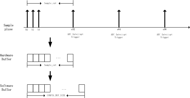
SARADC Overview
As shown in the figure above:
S1,S2: Indicates a sampling and conversion of the voltage on a certain channel of the ADC, and outputs 16 bits of data at a time; the sampling voltage range is 0 to 2.4v; a sampling time is 16 clocks.
Sample Rate: The reciprocal of the two sampling intervals is the sampling rate, which only takes effect in continuous mode.
- Sample Cnt: has two meanings. On the one hand, it represents the size of the ADC hardware Buffer in 16bits. The ADC stores the data obtained from each sample in the hardware Buffer; on the other hand, it also represents the interrupt reporting time point, that is, An interrupt is reported every number of sampling times;
Sample Cnt can be configured by API bk_adc_set_sample_cnt(), and the default value is 32.
ADC Hardware Buffer: It is the Buffer where the hardware stores the sampling data, the size is the same as Sample Cnt.
- ADC Software Buffer: The Buffer where the ADC driver stores sampling data. Every time an ADC interrupt is generated, the ADC driver will copy the data in the ADC Hardware Buffer to the ADC Software Buffer. Usually the size of the ADC Software Buffer is not smaller than the ADC Hardware Buffer.
Each time bk_adc_read()/bk_adc_read_raw() is called, the ADC Software Buffer will be cleared first, and then ADC sampling will be started until the ADC Software Buffer is full.
Taking the continuous mode as an example, the process of calling the ADC interface is as follows:
ADC Driver Init bk_adc_driver_init(): Generally speaking, the ADC_Driver will be initialized when the power is initialized, so this step is generally not required.
ADC Acquire bk_adc_acquire(): lock to access critical resources.
ADC Channel Init bk_adc_init(adc_channel): Turn on the power supply, clock source, etc., and configure the GPIO of the corresponding channel
ADC Config bk_adc_set_config(adc_config): Configure ADC according to needs
ADC Start bk_adc_start(): enable ADC module
- ADC Read bk_adc_read()/bk_adc_read_raw(): Turn on the ADC interrupt enable, wait for the interrupt, the hardware samples according to the configured sample rate, and store each sampling data in the Hardware Buffer,
After sampling sample cnt times, an ADC interrupt is generated, and the ADC driver moves the data in the ADC Hardware Buffer to the ADC Software Buffer, and finally disables the ADC interrupt enable
ADC Deinit bk_adc_deinit(adc_channel): Turn off ADC and remove related configuration.
ADC Release bk_adc_release(): Release critical resources