Overview
The RF test uses the WiFi_Test_Tool tool, which supports the test of WiFi and Bluetooth.
Hardware Connection
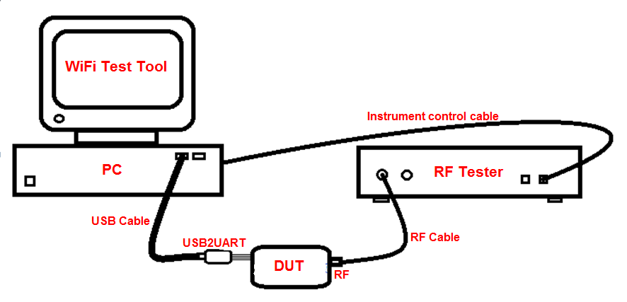
The hardware connection of the RF DUT module is shown in the figure: the DUT is connected to PC through a USB to serial cable, and the RF port at the other end is connected to the RF tester via the RF cable. The PC uses “WiFi Test Tool” to control the DUT, and also controls the instrument to measure the RF performance.
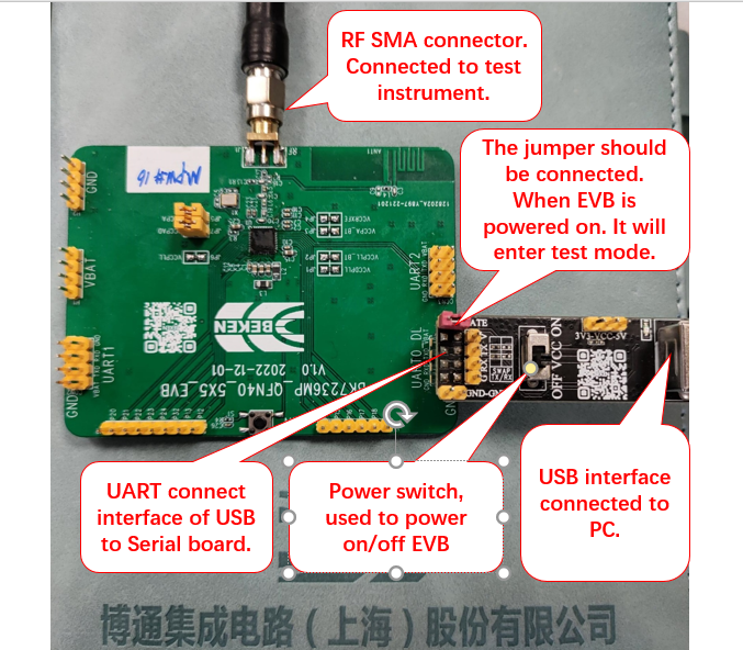
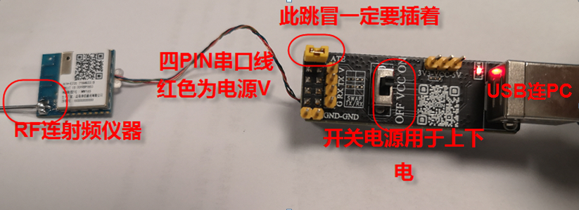
The lower part of the figure is a typical practical connection diagram. The connection method of different products is almost the same. The most important point is that the UART generally chooses UART0_DL interface, not other UART ports. And the TX pin of the UART0 must be connected to the 1K ohm resistor to the ground, so that it can enter the RF test mode (ATE mode) when the chip is powered on. When using the special serial board provided by BEKEN (the black board in the picture), you only need to plug the jumper marked ATE on the serial board, because the 1K resistor has been connected to the ground on the BEKEN board. If using a different serial board, add an additional 1K resistor to ground on the TX pin on your board.
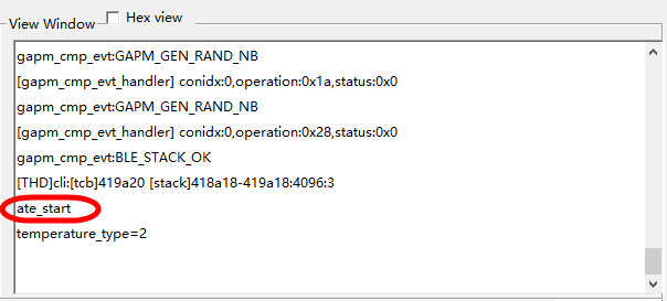
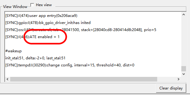
You can judge whether to enter ATE mode by looking at the log window printing of WiFi Test Tool when powering on, as shown in the figure below. Different products print “ate _start” or “ATE enabled = 1”, etc., which means that it has entered ATE mode and can be used to measure RF performance. If there is no print, please make sure that the 1K resistor is connected to ground or confirm with the software engineer whether the chip has really entered ATE mode.
WiFi Test Introduction
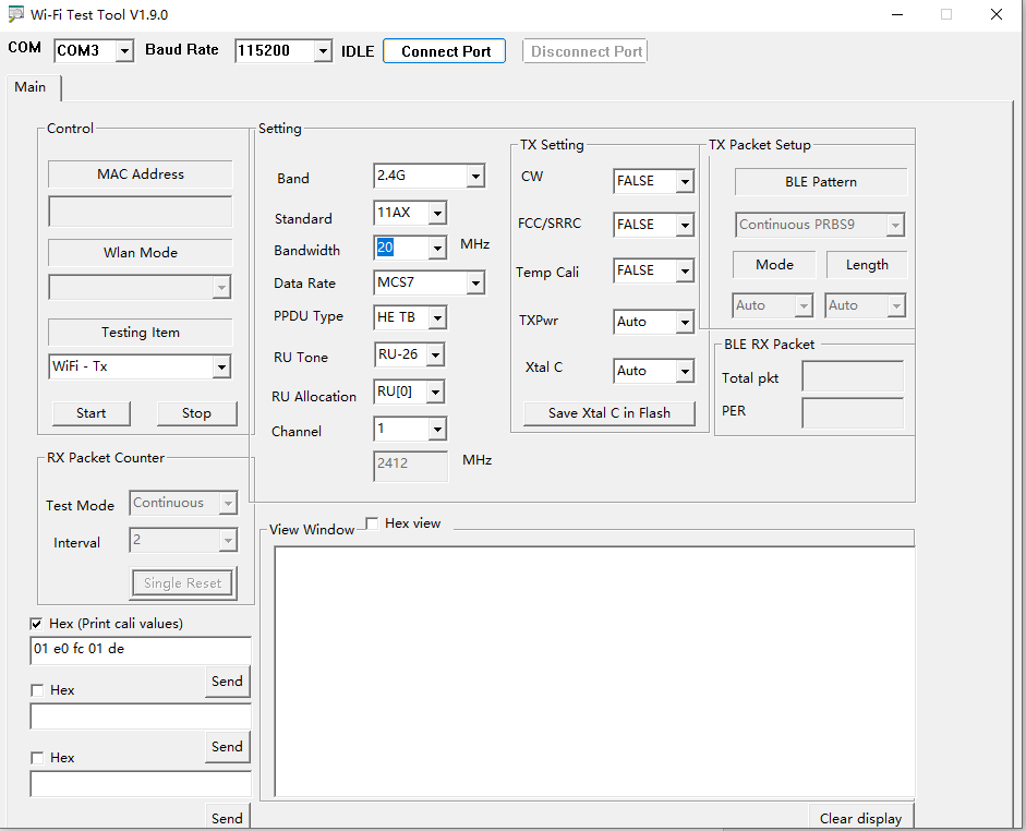
Serial Connection

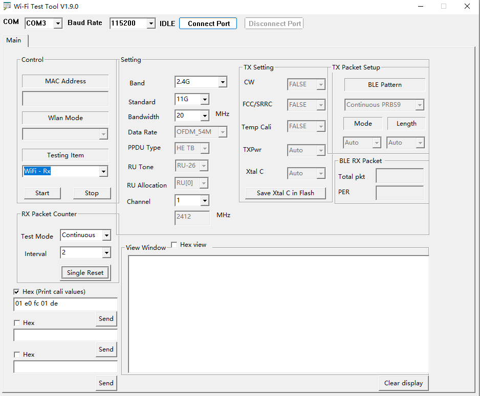
Real-time detection of the connected USB COM PORT, select the COM port used,
Baud Rate defaults to 115200,
Click the Connect Port button to connect the board. The status is changed from IDLE to OK!, which means that the serial port is successfully connected, otherwise please check the hardware and firmware.
Testing Item
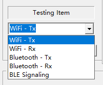
Select the Tx(transmit) or Rx(receive) mode of the board. Default is WiFi-Tx.
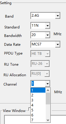
Band
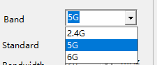
Select the band: 2.4G or 5G.
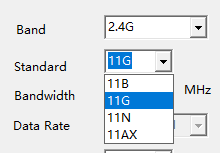
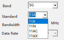
Standard
The 2.4G frequency band supports 11B, 11G, 11N, 11AX transmit/receive,
The 5G frequency band supports 11A, 11N, 11AC, 11AX transmit/receive,
Bandwidth
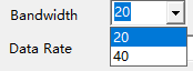
Currently, all products only support 20M and 40M bandwidth.
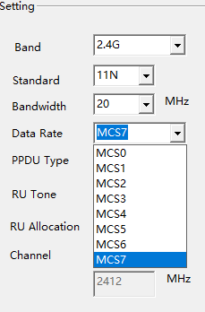
Data rate and Channel
|
|
All rates are supported by each protocol and all channels in every frequency band.
HE-TB RU
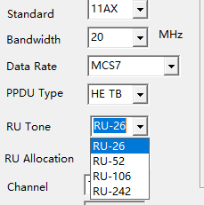
The RU tone and index checkboxes will only work when Standard is selected as 11AX and PPDU Type is HE TB.
Among them, RU Tone can choose four RUs: RU-26, RU-52, RU-106, and RU-242.
RU Allocation represents the position of the RU within the frequency band.
Start TX/RX
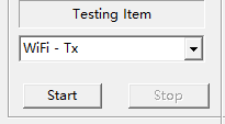
Start and Stop transmitting or receiving (only valid when connected to the board), and Stop and then Start when switching among different testing items.
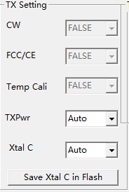
TX Setting
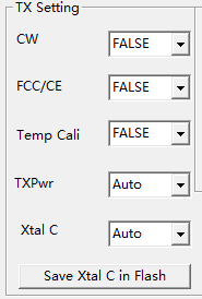
CW continuous-wave mode: Transmits single-carrier when TRUE, and transmits normal WiFi signal when FALSE. The default is FALSE.
FCC compliance certification: FALSE is normal mode, others are certification tests, standard optional: FCC, CE, SRRC. The default is FALSE.
Temp Cali real-time temperature calibration: If the temperature calibration is FALSE, the power factor value will not change with the temperature change. When it is TRUE, the power factor value will be adjusted according to the temperature change, , and it is generally used when testing high and low temperatures. The default is FALSE.
TXPwr Power Factor Setting: The power factor adjusts the transmit power, Auto uses the calibration value or the chip recommended value, and the default value is Auto. The maximum power factor range of different products is different, and the value range is as follows:
BK7239 products: value 0~127, 0.25dB,
Xtal C Crystal Capacitance Factor Setting: Adjust the internal crystal capacitance of the chip to modify the RF center frequency, Auto uses the calibration value or the chip recommended value, and the default value is Auto. The maximum capacitance factor range of different products is different, and the value range is as follows:
BK7239 products: the value is 0~255, the higher the value, the lower the frequency,
Save Xtal C in Flash: Save the current value of Xtal C to the Flash, and the new calibration value will be used the next time you select Auto. (This feature is only supported by some versions of firmware, so it is not recommended.)
Receive Packet
|

|
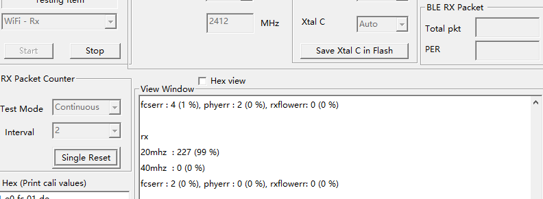
“RX Packet Counter”: For WiFi non-signaling receive test, you need to select “WiFi -Rx” in “Testing Item”.
“Test Mode” includes “Continous” for continuous receive test and “Single” mode for single receive test.
“Continous” mode: the instrument transmits continuously, the chip continues to receive. The datum are received within 2 seconds “Interval”. The correct rate of receiving packets is printed in the “View Window” box. Note that in this mode, the chip does not count the lost packets, and only calculates the correct rate of received packets. So the correct rate of the packets seen 99% (in parentheses in the figure) is Not credible, but the correct number of packets received before the parentheses in the above figure 227 is credible, You can use the signal source to send a large signal (to make sure that the instrument receives all the packets and does not lose any packets) to count how many packets the instrument has sent in total. And the 227 divide the total packets get the total packet error rate PER.
“Single” mode: click “Single Reset” first, then the instrument sends a fixed package (such as 1000bytes), then look at the number of 227 in the “View Window” box, and divide the correct number of packets received by the total number of packets sent by the instrument to get the correct rate value.
Bluetooth Test Introduction
Serial Connection
Real-time detection of the connected USB COM PORT, select the COM port used,
Baud Rate defaults to 115200,
Click the Connect Port button to connect the board. The status is changed from IDLE to OK!, which means that the serial port is successfully connected, otherwise please check the hardware and firmware.
Testing Item

Select Bluetooth-Tx
Data Rate
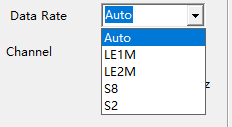
As shown in the figure, you can choose various rates of Bluetooth, Auto is the command of the old standard version of BLE 1Mbps, which is suitable for products with only BLE 1Mbps. LE1M is the command of the new standard version of BLE 1M, similar to the command format of LE2M, S8 and S2, and can be used in the new products that support LE2M and LE long range, both Auto and LE1M can test the 1Mbps rate.
Channel
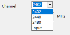
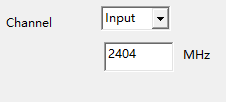
It supports three common channels and custom channel inputs.
TX Setting
Only the TXpwr Bluetooth power factor (0.25dB step) and Xtal C capacitance factor (frequency offset) work, and the others are WiFi-related configurations and have nothing to do with Bluetooth.
BLE Pattern
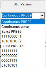
Valid only when the testing item Bluetooth-Tx is selected.
Continuous PRBS9 and Continuous wave are continuous PN9 waveforms and single carriers with a 100% duty cycle, and the rest are non-continuous brust waveforms (the default duty cycle is about 10%).
11110000 f1 and 10101010 f2 are used to test the Modulation Characteristics.
BLE RX Packet
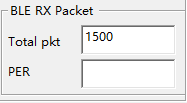
When the BLE receives the test, the total pkt needs to be changed to the number of packets transmitted by the signal source. When the source transmits the signal, the PER will be automatically calculated and displayed in the PER after clicking Stop on the testing item.
List of TX/RX Figures
Typical TX :
Typical RX: