Frequently Asked Questions (FAQ)
Does BK7239 Support 1-Line or 4-Line SDIO?
BK7239 supports both 1-line and 4-line SDIO modes. You can configure this using the CONFIG_SDIO_4LINES_EN macro in the project directory:
Set to Y to enable 4-line mode. Set to N to enable 1-line mode.
Does BK7239 Support 1.8V and 3.3V I/O Power Supply?
BK7239 supports both 1.8V and 3.3V I/O power supplies. The configuration is controlled using the CONFIG_GPIO_1V8_EN and CONFIG_GPIO_1V8_SRC_AUTO_SWITCH_EN macros in the project directory:
Set both macros to Y to enable 1.8V. Set both macros to N to enable 3.3V.
How to Configure the BK7239 SDIO Interrupt Pin
BK7239 uses GPIO external interrupts. You can configure it via GPIO_SDIO_NOTIFY_HOST in usr_gpio_cfg.h located in the project directory:
bk_idk/projects/wifi/controller/config/bk7239/usr_gpio_cfg.h
+ #define HOST_WAKEUP_CONTROLLER_GPIO_NO              (GPIO_1)
+ #define CONTROLLER_POWERUP_HOST_GPIO_NO             (GPIO_0)
+ #define GPIO_SDIO_NOTIFY_HOST                       (GPIO_34)
In the above, the Wi-Fi controller (1-Line project) is used as an example.The specific GPIO configuration depends on different hardware requirements and schematics. The above is for reference only.
beken_netdrv.ko fails to load
If the beken_netdrv.ko driver does not display a successful probe message or does not obtain a MAC address, check the following:
Ensure that the NOTIFY_HOST pin corresponds to a GPIO configured as an interrupt on the HOST side. Verify that the signal at both ends of the pin is correctly aligned. If necessary, use a logic analyzer to capture the signals for debugging.
Encountering CRC errors or frequent message resending after porting the code
If CRC errors occur, check whether the pull-up resistors on the module side for SDIO DATA0~DATA3 and CMD lines are properly matched. By default, the data and command lines on the module may not have pull-up resistors. Different MCU configurations may require dynamic adaptation based on the I/O drive current and SDIO voltage (3.3V/1.8V). The recommended resistance values are shown in the following table:
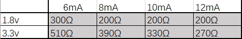
Figure 1. Voltage-current matching relationship with resistance
To verify the actual resistance values, use a multimeter and follow these steps: Measure the resistance between VDDIO and each SDIO_DATA pin.
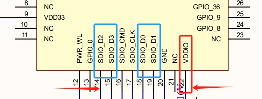
Figure 2. SDIO GPIO & VDDIO
Checking GPIO Configuration
Refer to bk_idk/projects/wifi/controller_4wire/config/bk7239/usr_gpio_cfg.h to check whether the GPIOs are correctly configured for SDIO. Ensure that the required four SDIO pins are properly set. If not configured correctly, the SLAVE side may not receive signals, affecting normal CMD transmission and reception.