Low Power Development Guide
Introduction of Low Power Status
- The system supports different sleep modes:
active
normal sleep
low voltage
deep sleep
super deep sleep
shut down
Supported wake-up modes:
#sleep mode
GPIO
RTC
WIFImac
BTdm
TOUCH
normal sleep
Y
Y
Y
Y
Y
low voltage
Y
Y
Y
Y
Y
deep sleep
Y
Y
N
N
Y
super deep sleep
Y
Y
N
N
N
active(work)
The CPU is in working and WIFI and BT can receive and send data.
normal sleep(normal sleep)
When rtos does not have a task to deal with, the system enters the idle task, and the CPU enters the WFI sleep in the idle task. When there is any interruption, it can exit the wfi state and go to work.
low voltage(low voltage sleep)
low voltage sleep mode is a relatively more power save sleep mode.In the sleep mode the system only has a 32k clock, and only a part of hardware modules are working that except AON module work ,other hardware modules are suspended(not run)
- When it wakes up and exit from the low voltage sleep mode, the voltage of dvdddig is return to the work voltage(1.1v).
when it is in the low voltage sleep mode, the (GPIO,RTC,Touch,WIFI,BT) wakeup source can let the system wake up from the low voltage sleep mode. Attention: WIFI and BT according the usage scenario enter the low voltage sleep mode, which is special.
it select which 32k source(external 32k, rosc, external 26M division 32k), which according the usage scenario.
In order to achieve the optimal power consumption, the modules that are not needed, please close them before enter the low voltage, and then restore them when exit the low voltage.
deep sleep(deep sleep)
Deep sleep is a relatively more power-saving sleep mode.In the sleep mode the system only has a 32k clock,and only AON modules are working, other modules power off.
- when it wakes up,the system exit the deep sleep state,then the system reset.
In the deep sleep mode,the wakeup source(GPIO,RTC,Touch)can let the system exit the deep sleep mode.
The rosc is the default 32k source in the sleep mode.
super deep sleep(super deep sleep)
The difference from deepsleep is that in this mode, the AON power domain are also powered off, and only some analog areas have power; The digital wake-up source does not work and can only rely on analog GPIO or RTC wake-up.
shut down(shut down)
all the chip is powered off
The API of Low Power
To simplify the low-power development process, the SDK encapsulates low-power operations into relevant interfaces. The main interfaces are described as follows.
1 // Ask Controller to goto low voltage sleep
2 void ctrl_if_start_lv_sleep(void);
3 // Ask Controller to goto deep sleep
4 void ctrl_if_start_deep_sleep(void);
5 // Ask Controller to wakeup
6 bk_err_t ctrl_if_exit_sleep(void);
Important
The sleep and wake-up of the Controller are closely related to the main control. For low-power control, the specified interfaces must be used to ensure that communication with the main control is not affected
Host Power On/Off Control
To simplify the control of the main control’s power on and off, the SDK provides interfaces that encapsulate these operations. The main interface descriptions are as follows:
1 // Power on Host
2 bk_err_t ctrl_if_power_up_host(void);
3 // Power off Host
4 bk_err_t ctrl_if_power_down_host(void);
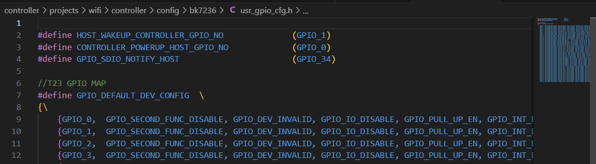
The above interfaces operate the GPIO to control the main control’s power on and off. The specific GPIO to use is specified by CONTROLLER_POWERUP_HOST_GPIO_NO.
Important
The power on and off of the main control directly affects the interaction between the Controller and the main control. Please ensure that the power on and off operations use the above interfaces rather than directly operating the GPIO
Data Filter Configuration
By default, TCP/IP data received by the Controller’s Wi-Fi module is transferred to the Host rather than the local TCP/IP protocol stack. In low-power keep-alive scenarios, since the main control is in a power-off state, the keep-alive application runs on the Controller side. In this case, TCP/IP data received by the Controller’s Wi-Fi module needs to be sent to the local TCP/IP protocol stack.
To distinguish which data should be sent to the local TCP/IP protocol stack, the Controller SDK provides a data filter interface:
Function defines: void cif_filter_add_customer_filter(uint32_t ip, uint16_t port), where ip is the source IP address of the data, and port is the source port number.
Note that the IP address is in network order.
For example, during low-power keep-alive, the server’s IP address is 111.222.111.123, and the port number is 1234.
The IP address in network order as a 32-bit unsigned hexadecimal is 0x6FDE6F7B.
You can add the corresponding IP and port number to the filter using cif_filter_add_customer_filter(0x6FDE6F7B, 1234).
Controller Low-Power Wake-Up Control
As described in the low-power state introduction, when the system enters low-power sleep or deep sleep, software execution is suspended. If the developer wishes to execute certain processes during sleep, specific wake-up sources must be used to wake the system from sleep.
Low-Power Sleep Wake-Up
During low-power sleep, common wake-up methods include Wi-Fi (server keep-alive wake-up), GPIO (such as button presses), and RTC. If Wi-Fi remains connected to the router during low-power sleep, the router will automatically wake up the device to receive data and report it to the corresponding application when it sends data. Therefore, Wi-Fi wake-up does not require special attention from developers.
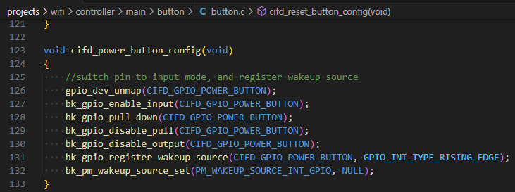
GPIO Wake-Up
When using GPIO as a wake-up source, specific configurations for GPIO and registration of GPIO interrupts are required. For reference, please look at the wake-up code example for buttons in the demo project.
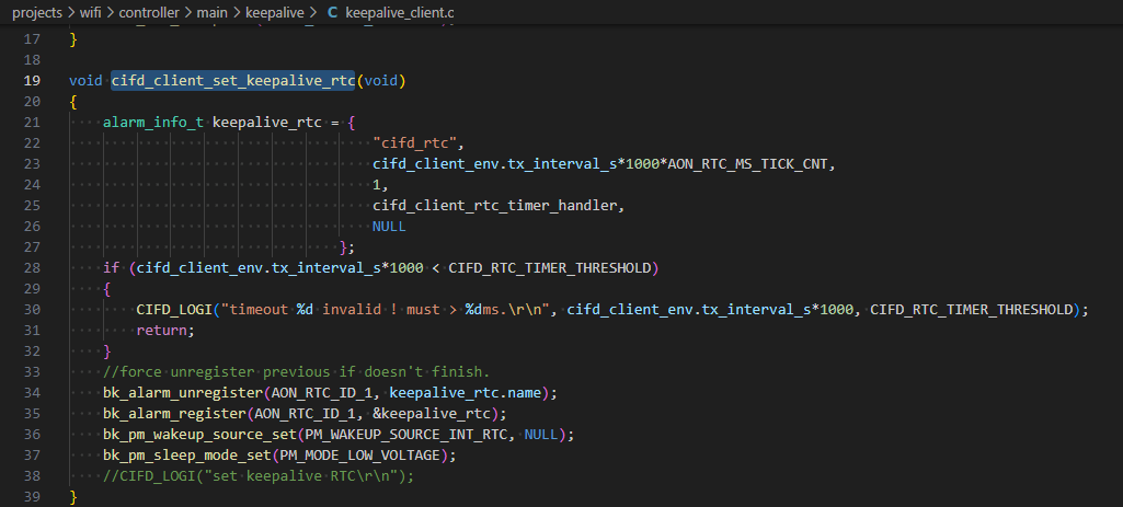
RTC Wake-Up
RTC wake-up requires configuration of the RTC timer. For reference, please look at the following code in the demo project:
Deep Sleep Wake-Up
In deep sleep, Wi-Fi cannot maintain a connection, so it cannot wake up the system via Wi-Fi. The wake-up methods for GPIO and RTC are similar to those in Low-Power Sleep Wake-Up
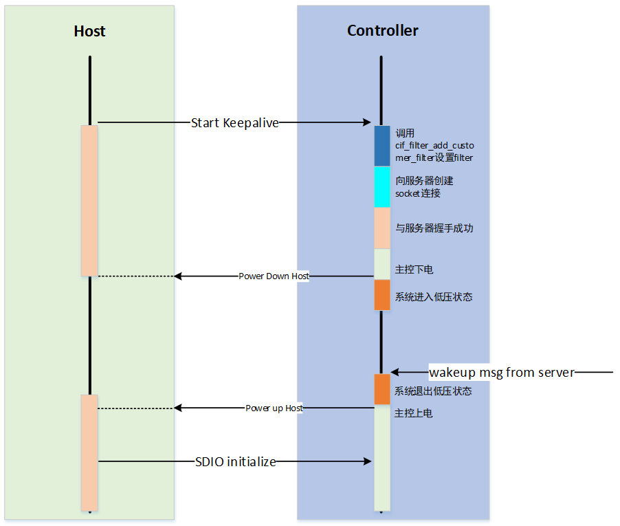
Low Power Keep-Alive Development
The low power keep-alive wake-up process is established through the following steps:
Configure the filter using
cif_filter_add_customer_filter.Establish a socket connection with the server.
After a successful handshake with the server, invoke the ctrl_if_power_down_host interface to power down the host.
Call ctrl_if_start_lv_sleep to put the system into a low power state.
The process to exit low power keep-alive mode is as follows:
Upon receiving a network wake-up message, invoke ctrl_if_exit_sleep to exit the low power state.
Call ctrl_if_power_up_host to power up the host.
Re-establish the connection between the host and the server.