AP(SMP) and CP Architecture
Architecture Overview
BK7258 consists of three cores. To simplify application development, the Armino SDK introduces a new AP+CP architecture, that is, the SMP (CPU1 + CPU2) + CPU0 mode. In this architecture, CPU1 and CPU2 form an SMP system called AP, and CPU0 is a single-core system called CP.
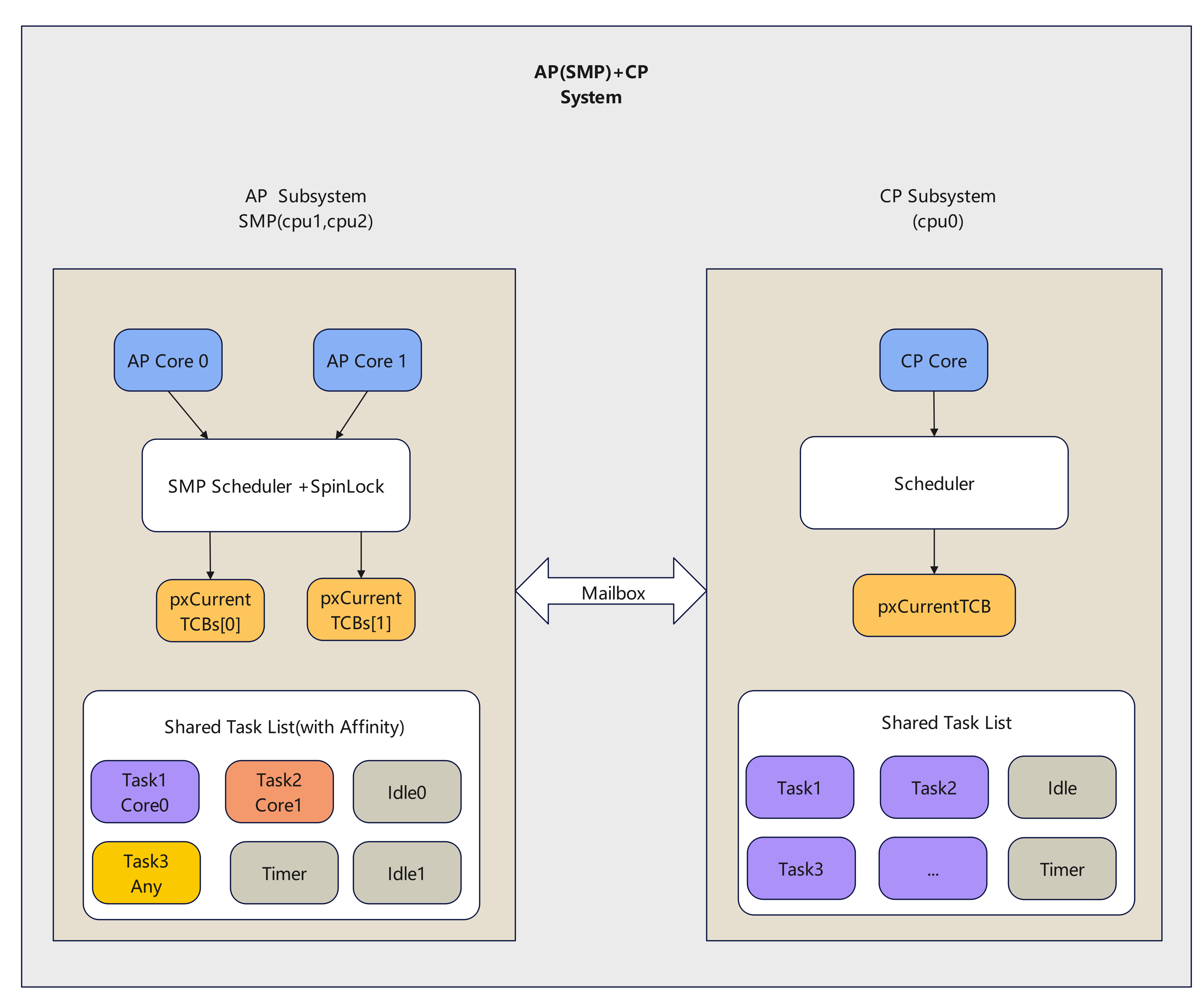
AP(SMP)+CP Architecture
As shown in the figure above, AP and CP are two independent subsystems. Their independence is reflected in the following aspects:
CP code is completely independent, containing only Wi-Fi, BLE, and a small number of basic peripherals, and runs on CPU0.
AP code is also completely independent, covering multimedia solutions. Customer development focuses on AP, with CPU1 and CPU2 running in SMP (Symmetric Multi-Processing) mode.
From the application perspective, CP runs Wi-Fi, BLE, the low-power LWIP protocol stack for keep-alive, and the required peripherals. AP runs multimedia modules, provides the LWIP protocol stack for upper layers, and exposes frequently used peripherals for applications. AP and CP exchange data through the mailbox plus shared memory. From the application perspective, they communicate through a virtual UART interface. AP logs are sent to CP through the mailbox and then output from UART0.
In the new architecture, all user development happens on AP. Users no longer need to handle CP-side development. CP functionality, as well as interactions between AP and CP, are handled by the lower layers.
The new architecture also adopts a refreshed SDK directory structure, as shown below:
ubuntu240:~/bk_avdk_smp$ tree -L 2
├── ap
│   ├── CMakeLists.txt
│   ├── components
│   ├── docs
│   ├── include
│   ├── Kconfig
│   ├── Makefile
│   ├── middleware
│   ├── properties
│   └── requirements.txt
├── cp
│   ├── CMakeLists.txt
│   ├── components
│   ├── docs
│   ├── include
│   ├── Kconfig
│   ├── Makefile
│   ├── middleware
│   ├── properties
│   └── requirements.txt
├── docs
│   ├── bk7258
│   └── version.json
├── LICENSE
├── Makefile
├── projects
│   ├── app
│   ├── app_ab
│   ├── doorbell
│   ├── lvgl
│   └── test
├── README_CN.md
├── README.md
└── tools
    ├── armino_doc.py
    ├── bk_bootloader_post.py
    ├── bk_smp_auto_partition.py
    ├── bk_smp_package.py
    ├── build_main.mk
    ├── build_tools
    └── env_tools
AP and CP code reside in their respective directories, remaining completely independent. The projects directory contains ap_main and cp_main folders, which hold customer-specific code for AP and CP respectively.
Based on this directory structure, the build process is as follows:
According to the project’s partition table configuration, the automatic partition tool generates the partition table and related files.
Compile the BK7258 AP system to generate the SMP image.
Compile the BK7258 CP system to generate the bootloader and cp.bin image.
Package bootloader.bin, cp.bin, and ap.bin into all-app.bin according to the partition table.
System Control
Resource Allocation
Each core contains 16 KB of ITCM and 16 KB of DTCM space. SRAM, PSRAM, and flash are shared between AP and CP.
The SDK allocates memory for AP and CP based on their resource requirements. If upper-layer applications need to adjust the allocation, edit ram_regions.csv in the project. See RAM Region Configuration for details.
To make full use of system resources and address the limited SRAM size, the new architecture also adjusts the SRAM layout.
The current layout (taking the doorbell project as an example) is as follows:
/***************************************************************************
|--spinlock--|--hardware acc--|--ap sram--|--cp sram--|--pwr-mng--|--swap--|
****************************************************************************/
Note
We recommend not changing this layout arbitrarily, but you can adjust the SRAM size for AP and CP according to actual needs.
Considering that PSRAM may need to be powered down, CP usage of PSRAM is limited to temporary scenarios (such as dynamic logs that are released after use). Do not place tasks, queues, or code in PSRAM on the CP side.
System Reboot
The architecture adopts a full reset scheme, where if the CP or AP system encounters an exception, the entire system is fully reset.
It also supports upper-layer applications actively calling the bk_reboot interface to perform a reset.
System Watchdog
Since there is only one instance of the watchdog hardware resource, it is placed on the CP for management. The following macros are used to configure it:
CONFIG_INT_WDT=y
CONFIG_INT_WDT_PERIOD_MS=8000
CONFIG_TASK_WDT=y
CONFIG_TASK_WDT_PERIOD_MS=16000
The watchdog is serviced on the CP. If it is not fed within the configured time window, the system triggers a restart.
There is no hardware watchdog on the AP side. Instead, an inter-core heartbeat mechanism detects whether the AP is operating normally.
Inter-Core Heartbeat
After startup, the AP periodically sends heartbeat packets to the CP (default interval: 2 seconds). This feature is controlled by the macro CONFIG_SLAVE_HEART_BEAT and is enabled by default.
If the CP does not receive a heartbeat from the AP within the configured timeout (aligned with the INT WDT timeout), the AP is considered offline and the system triggers a restart.
System Debug
The system’s log is managed by the CP. If it’s a log from the CP side, it’s directly output through the serial port. If it’s a log from the AP side, the AP sends it to the CP through the mailbox, and then the CP outputs it through the serial port.
CP logs do not have any prefix, while AP logs are prefixed with ap0 or ap1.
Here is an example of partial log output during system startup:
os:I(2):
os:I(7):mem_type start    end      size
os:I(7):-------- -------- -------- --------
os:I(7):itcm     0x20     0x3e88   15976
os:I(7):dtcm     0x20000000 0x200035f8 13816
os:I(7):ram      0x28064e00 0x2809e7f8 236024
os:I(7):non_heap 0x28064e00 0x280853a0 132512
os:I(7):iram     0x8064000 0x8064c40 3136
os:I(7):data     0x28064e00 0x28066128 4904
os:I(7):bss      0x28066140 0x2808539c 127580
os:I(7):heap     0x280853a0 0x2809e7f8 103512
os:I(7):psram    0x60700000 0x60720000 131072
os:I(8):create flash_svr, tcb=28088e00, stack=[280887d8-28088dd8:1536], prio=3
flash:I(8):id=0xc86517
ef:I(9):ENV start address is 0x007FA000, size is 8192 bytes.
ef:I(11):EasyFlash V4.1.0 is initialize success.
(11):ate enabled is 0
(11):driver_init end
sensor:I(12):saradc low value:[9d7]
sensor:I(12):saradc high value:[13aa]
sensor:I(12):sdmadc low value:[6eaf]
sensor:I(12):sdmadc high value:[89b4]
init:I(12):reason - power on
init:I(12):regs - 0, 0, 0
init:I(12):armino rev:
init:I(12):armino soc id:53434647_72360101
bk_init:I(12):armino app init: Jun  6 2025 15:48:25
bk_init:I(12):verify id: unknown
bk_init:I(12):APP Version: unknown
nv:I(12):vnd_cal_version = 24-04-10 00:00:00

......

bt_ipc:I(105):open channel: 67 on CPU
bt_ipc:I(105):bt_ipc_init success
bluetoot:I(105):bk_bluetooth_init ok
os:I(105):create rosc_calib, tcb=28095028, stack=[28094000-28095000:4096], prio=1
(106):user app entry(0x2033561)
(106):boot_cp1 9 0 0x0 [0][0x28068388]E_1
(106):boot_cp1 9 0 0x0 [0]E_2
(106):reset_cpu1_core at: 02150000, start=1
ap0:AP:E(13):Mailbox send data fail[ret:-4103]
ap0:os:I(13):psram:0x60720000,size:655360
ap0:os:I(1):
ap0:os:I(13):mem_type start    end      size
ap0:os:I(13):-------- -------- -------- --------
ap0:os:I(13):itcm     0x20     0xa0     128
ap0:os:I(13):dtcm     0x20000004 0x20000004 0
ap0:os:I(13):ram      0x28010600 0x28060ff8 330232
ap0:os:I(13):non_heap 0x28010600 0x2801a408 40456
ap0:os:I(13):iram     0x8010000 0x8010508 1288
ap0:os:I(13):data     0x28010600 0x28010f44 2372
ap0:os:I(13):bss      0x28011d40 0x2801a404 34500
ap0:os:I(13):heap     0x2801a408 0x28060ff8 289776
ap0:os:I(13):psram    0x60720000 0x607c0000 655360
ap0:ef:I(14):ENV start address is 0x007FC000, size is 8192 bytes.
ap0:ef:I(42):EasyFlash V4.1.0 is initialize success.
ap0:(43):driver_init end
ap0:init:I(43):reason - power on
ap0:init:I(43):regs - 0, 0, 0
ap0:init:I(43):armino rev:
ap0:init:I(43):armino soc id:53434647_72360101
ap0:bk_init:I(43):armino app init: Jun  6 2025 15:48:16
ap0:bk_init:I(43):verify id: unknown
ap0:bk_init:I(43):APP Version: unknown
ap0:gpio:I(43):bk_gpio_driver_init:has inited
The system supports debugging of modules through CLI commands. CP-side CLI commands do not require any prefix, while AP-side CLI commands must be prefixed with “ap_cmd”.
Here is an example of inputting the “memshow” command on the CP side and AP side:
CP side
memshow (input command)

os:I(2811):create shell_handle, tcb=28086f60, stack=[28085338-28086f38:7168], prio=5
cli:I(2812):================Static memory================
os:I(2812):
os:I(2812):mem_type start    end      size
os:I(2812):-------- -------- -------- --------
os:I(2812):itcm     0x20     0x3e88   15976
os:I(2812):dtcm     0x20000000 0x200035f8 13816
os:I(2812):ram      0x28064e00 0x2809e7f8 236024
os:I(2812):non_heap 0x28064e00 0x28085120 131872
os:I(2812):iram     0x8064000 0x8064c60 3168
os:I(2812):data     0x28064e00 0x28066120 4896
os:I(2812):bss      0x28066140 0x2808511c 126940
os:I(2812):heap     0x28085120 0x2809e7f8 104152
os:I(2812):psram    0x60700000 0x60720000 131072
cli:I(2812):================Dynamic memory================
name    total   free    minimum   peak
heap        104152  35440   28576   75576
psram       131072  0       0       131072

AP side
ap_cmd memshow (input command)
os:I(2009):create shell_handle, tcb=280871e0, stack=[280855b8-280871b8:7168], prio=5

$ap0:cli:I(1857):================Static memory================
ap0:os:I(1857):
ap0:os:I(1857):mem_type start    end      size
ap0:os:I(1857):-------- -------- -------- --------
ap0:os:I(1857):itcm     0x20     0xa0     128
ap0:os:I(1857):dtcm     0x20000004 0x20000004 0
ap0:os:I(1857):ram      0x28010600 0x28060ff8 330232
ap0:os:I(1857):non_heap 0x28010600 0x2801a408 40456
ap0:os:I(1857):iram     0x8010000 0x8010508 1288
ap0:os:I(1857):data     0x28010600 0x28010f44 2372
ap0:os:I(1857):bss      0x28011d40 0x2801a404 34500
ap0:os:I(1857):heap     0x2801a408 0x28060ff8 289776
ap0:os:I(1857):psram    0x60720000 0x607c0000 655360
ap0:cli:I(1857):================Dynamic memory================
name    total   free    minimum   peak
heap        289776  250728  246392  4338
When the system encounters an exception, if the macro CONFIG_DEBUG_FIRMWARE or CONFIG_DUMP_ENABLE is enabled, a dump log will be output. If the exception occurs on the CP side, the dump log will be directly output through the serial port.
If the exception occurs on the AP side, the dump log will be transmitted to the CP side through the mailbox, and then the CP side will control the serial port to output the dump log.
Note
To maintain compatibility, AP-side CLI commands are uniformly prefixed with “ap_cmd”, because at this time, the AP is an SMP system, and the two cores can be considered as a whole.
However, AP-side log output may be prefixed with either “ap0” or “ap1”, which is used to distinguish which specific core is running the code and outputting the log.
for example:
ap1:(634010):cpu2_test_task run core: 2
ap0:(634010):cpu1_test_task run core: 1
ap1:(636010):cpu2_test_task run core: 2
ap0:(636010):cpu1_test_task run core: 1
CP Subsystem
The CP side provides streamlined functionality focused on connectivity and management:
Run Wi-Fi, BLE, and the LWIP protocol stack used for low-power keep-alive
Manage system log output and respond to CLI commands
Maintain the inter-core heartbeat to detect AP online status
Handle overall low-power management for the system
AP Subsystem
Overview
According to the new architecture design, BK7258 supports a dual-core SMP architecture in which both cores share all peripherals and memory resources. Each core also owns private resources such as NVIC and cache. The cores exchange necessary information through the mailbox.
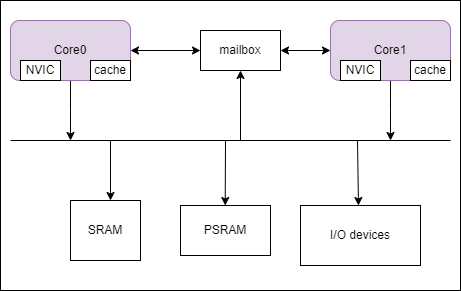
SMP Architecture
Note
In the diagram, Core 0/Core 1 refers to the logical core ID, which will be explained in the next section. From now on, we will use the logical ID to refer to the cores.
In SMP, the mailbox refers to a physical mailbox channel used to transmit necessary information between the two cores.
Core ID Management
In this architecture, the SMP system runs on physical CPU1 and CPU2.
From the kernel perspective, logical IDs are used, meaning tasks always see CPU indices as 0, 1, and so on regardless of the actual physical core.
From the application perspective, certain resource configurations must bind to a specific physical core. Call rtos_get_core_id() in os.h to obtain the physical ID; it returns 1 or 2 for physical CPU1 or CPU2.
During SMP startup, each core records its own ID in a predefined location.
Important
Use only rtos_get_core_id() to obtain the physical CPU ID. It returns CPU1_CORE_ID or CPU2_CORE_ID,
corresponding to physical CPU1 and CPU2.
SMP Startup Process
During the system’s boot and initialization phase, there is only one context, which can only be processed by one processor.
Therefore, for SMP systems, there is usually a primary core that starts first (called the primary core), which is responsible for initializing the entire system’s resources, while other cores wait for these resources to be ready before starting work.
For the new SMP architecture, the primary core is Core 0 (note that this refers to the logical ID), which is responsible for booting the system’s resources, such as peripherals, memory, etc.
After Core 0 has finished initializing the resources, it will release Core 1, allowing Core 1 to start, and then begin scheduling system tasks. At this point, the entire system is running.
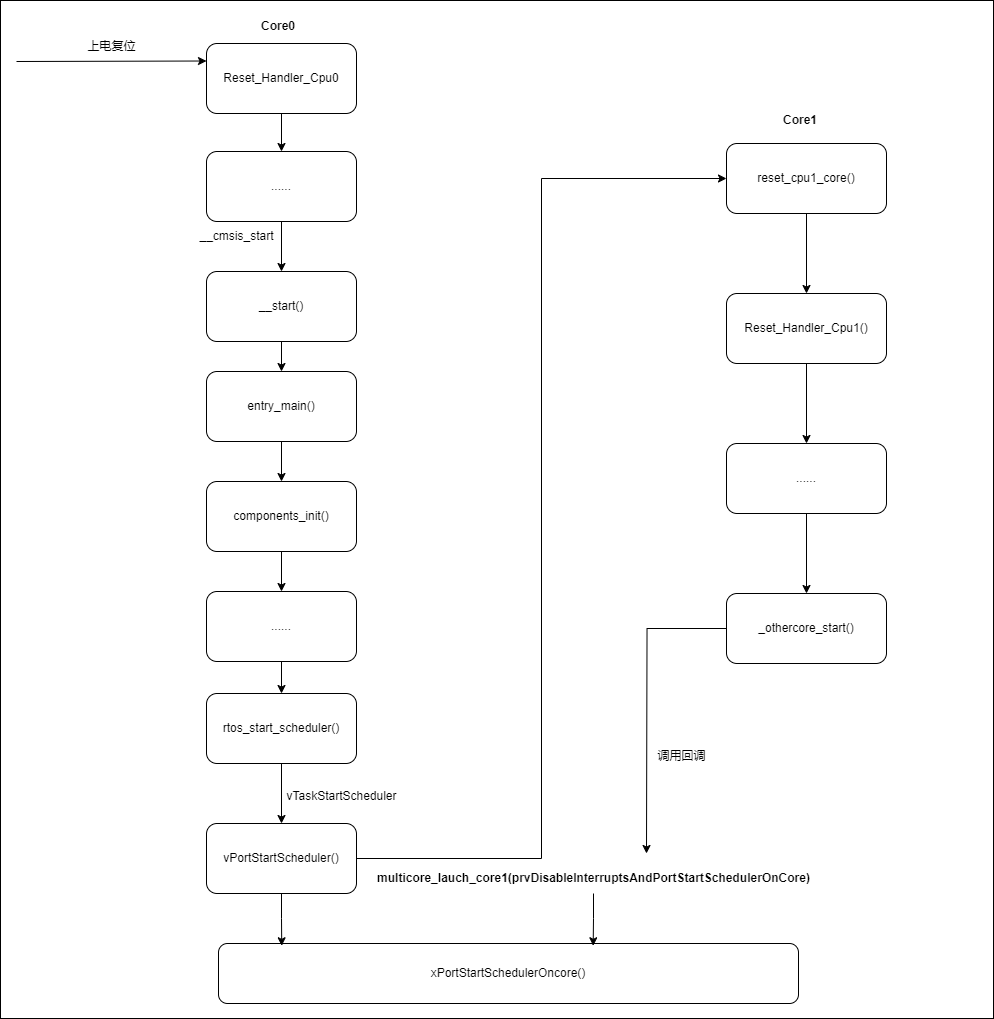
SMP Startup Process
SMP Programming Notes
From the perspective of software timing, SMP systems and single-CPU systems have some differences in programming. These differences mainly lie in:
Although peripherals and memory resources are shared, simultaneous access by multiple CPUs requires critical-section protection. Traditional interrupt-disable methods are insufficient; combine interrupt masking with spin locks. See SMP Critical Section.
Each core has its own interrupt controller, but a given peripheral interrupt is typically handled by one designated core. Configure interrupt routing as needed. See Interrupt Management.
Upper-layer tasks can be pinned to a specific CPU or left unbound for the kernel to schedule. For unbound tasks, pay special attention to exclusive access protections for shared resources. See OS Abstract API.