UART
1 Functional Overview
The BK7258 has a total of 2 groups of PWM, with each group having 6 channels.
For each group of PWM, only one of the adjacent channels can be independently output ((0,1) adjacent, (2,3) adjacent, (4,5) adjacent), and simultaneous output will cause mutual interference.
Each group of PWM can implement 3 complementary outputs, as shown in the table in the overview. Only PWMx’s CH0 and CH1, CH2 and CH3, and CH4 and CH5 can be configured as complementary outputs, with corresponding dead time registers available for configuration. This method is more precise, but the channels are fixed.
PWM1’s CH0, CH2, CH4 and PWM2’s CH0, CH2, CH4 can be combined to form a complementary output using any two channels, implementing the complementary function through software. This method is more flexible, but the precision is not as good as the hardware implementation.
Additionally, when applying to lamps or motors, it is not recommended to use P8/P22, P9/P23.
The BK7258 has 12 PWM output channels. When outputting, the clock source is 26M, and the period and duty cycle of each channel can be configured. The channels are as follows:
channel
GPIO
channel
GPIO
0
GPIO6/GPIO18
6
GPIO32
1
GPIO7/GPIO19
7
GPIO33
2
GPIO8/GPIO22
8
GPIO34
3
GPIO9/GPIO23
9
GPIO35
4
GPIO24
10
GPIO36
5
GPIO25
11
GPIO37
Note
When supporting multiple GPIOs, please note the default PWM channel corresponding GPIO configuration. The configuration file is located in gpio_map.h, specifically in the GPIO_PWM_MAP_TABLE.
2 Code path
demo path:
components\bk_cli\cli_pwm.c
3 CLI Command Overview
Demo Run Dependencies: Macro Configuration:
NAME
Description
File
value
CONFIG_PWM
support PWM
middleware\soc\bk7258\bk7258.defconfigy
The demo supports the following commands as listed in the table:
Command
Param
Description
pwm_driver init {26M|DCO}
26M|DCO:clk source,default 26M
init the resoure common to all PWM channels
pwm_driver deinit
none
free all resource related to pwm
pwm {chan} init {period_v} {duty_v}
[duty2_v][duty3_v]
chan: pwm channel
power up and config the pwm channel, set the period and duty cycle
note: this chip supports 3 duty cycle , parameter duty2_v and duty3_v are optional
period_v:pwm periord
duty_v: duty cycle
duty2_v: second level reversal
duty3_v: third level reversal
pwm {chan} duty {period_v} {duty_v}
[duty2_v] [duty3_v]
chan: pwm channel
configure the period and duty cycle.
note: parameter duty2_v and duty3_v are option.
period_v:pwm periord
duty_v: duty cycl
duty2_v: second level reversal
duty3_v: third level reversal
pwm {chan} {start|stop|deinit}
chan: pwm channel
read data_size bytes of data from
start|stop|deinit:
pwm {chan} signal {low|high}
chan: pwm channel
set the initial signal to high|low
low|high: initial signal level
pwm_group init {chan1} {chan2}
{period} {chan1_duty} {chan2_duty}
chan1: pwm channel
init the PWM group
The PWM group is a channel pair that has following attributes: -The period is same -The initial signal level is opposite -Start and stop at the same time
chan2: pwm channel
period: pwm periord
chan1_duty: chan1 duty cycle
chan2_duty: chan2 duty cycle
pwm_group {start|stop|deinit}
chan: pwm channel
start|stop|deinit the PWM group
start|stop|deinit:
pwm_group config {group} {period}
{chan1_duty} {chan2_duty}
group: pwm channel
Configure the duty and period of a PWM group
period: pwm periord
chan1_duty: chan1 duty cycle
chan2_duty: chan2 duty cycle
pwm_capture {chan} capture_example
chan: pwm channel
calculate the PWM Input Signal’s Period and Duty Cycle
capture_example
4 Demo Introduction
The demo execution steps are as follows:
Prepare a logic analyzer and connect it as follows:
pwm channel 0----GPIO18

pwm channel 1----GPIO19
PWM Independent Output Mode
Initialize the PWM driver:
pwm_driver init
2.1 Ordinary Output
pwm 0 init 200 100 0 0 25 //Duty cycle 50%
pwm 0 start
Waveform as follows:
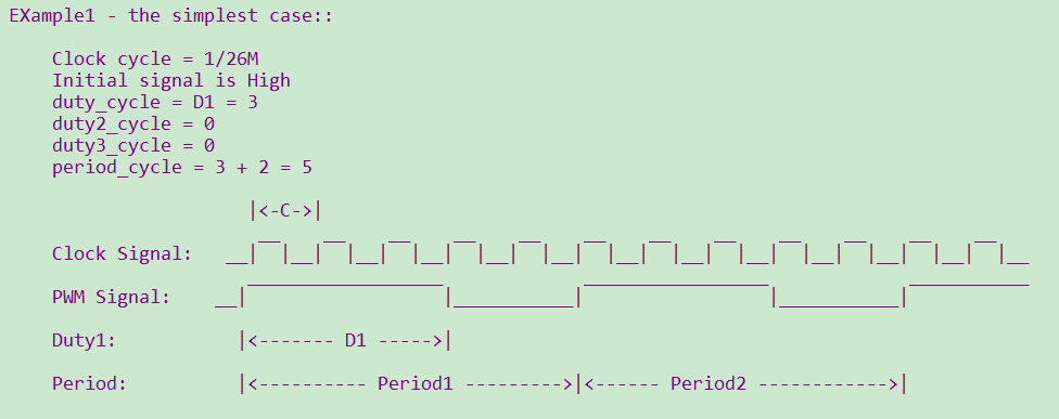
Figure 1. Outputting a 60% Duty Cycle PWM
Note
According to the parameter configuration, the duty cycle can be adjusted within the same period. However, each adjustment will only take effect in the next period. When setting the PWM init and duty, it must be ensured that period > (D1+D2+D3).