UVC
Overview
This section mainly describes how to adapt USB on the current CPU.
Supported Functions
Supports a maximum of 3 UVC outputs simultaneously.
Supports dual - stream, which means a single camera can output two types of code streams simultaneously.
By default, it supports a maximum of 8 resolutions. If the camera supports more resolutions, software modifications are required accordingly.
Users need to enable the corresponding functions by configuring parameters according to their own application scenarios.
Code Flow
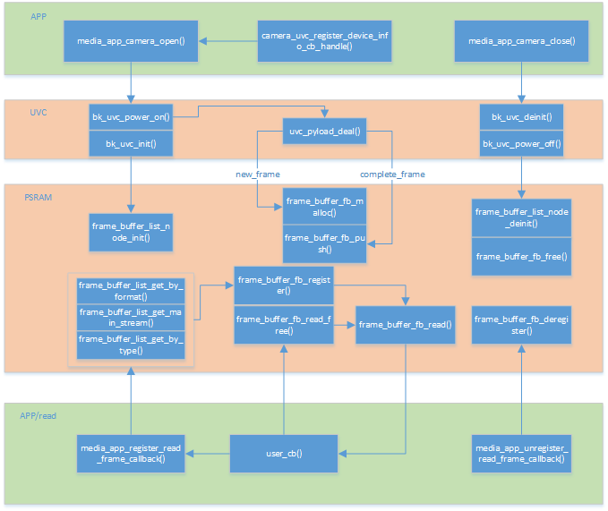
Figure 1. UVC process flow chart
Note
In this solution, all large - memory uses PSRAM. Currently, the SRAM solution is not supported. For the PSRAM - free solution, please refer to BK7257.
Common Issues
When using UVC, you may encounter some common problems. Here are some debugging methods.
Q: After calling the uvc open interface, the camera is not enumerated (there is no prompt for successful connection).
A: This problem is usually caused by the camera not being powered on or insufficient power supply. It is generally recommended to supply 5.0V voltage to the USB. BK7258 controls the USB LDO through GPIO28. Pulling it high enables the USB power, and pulling it low powers off the USB. You can configure it through the following macro:
marco
value
implication
CONFIG_USB_VBAT_CONTROL_GPIO_ID
0x1C
gpio control hub power, default 0x1C
Q: The enumeration is successful, but no image is displayed.
A: This problem generally requires checking whether the parameters are configured incorrectly. For example, the camera may not support the resolution you configured, and you need to re - configure it. When the resolution is configured incorrectly, the following log will be printed: “uvc_camera_set_param, not support this format or resolution, please check!”. If this is not the case, you need to capture packets for analysis to see if the UVC data packets are normal. The packets should include a header + valid data, and the valid data should be normal values.
Q: The frame rate is lower than expected.
A: The so - called “expected” is relative to a PC. For example, if you configure 30fps but only get half or much lower in reality, plug the camera into a computer to analyze whether the frame rate is also low, which can rule out the influence of the camera itself. If it’s not the camera’s problem, consider whether it’s an issue with the SDK. This requires logic analyzer analysis or packet capture analysis using a protocol analyzer.
Q: The image has abnormal screen - cutting or is incomplete.
A: In this case, you generally need to check whether the transmission mode (ISO/BULK) is configured incorrectly, and then check whether the upper - layer packet - unpacking logic is wrong.
Q: The image has abnormal halos and distortion.
A: This is generally considered to be a problem with the camera itself. Plug it into a PC to analyze whether the same problem occurs.
Q: The abnormal log “uvc_camera_urb_malloc failed” appears, or there is abnormal screen - cutting during synchronous image output.
A: The reason for this problem is that the USB fails to allocate URB to store data in the FIFO. The failure to allocate is due to all USB URB resources being used up, with no idle URB available. There are two root causes:
- One is that the efficiency of consuming (parsing) the URB storing FIFO data is too low, or the process is stuck, resulting in all idle URB being consumed and the URB pool being full of URBs to be parsed.
Reference code: “./ap/bk_uvc/bk_uvc.c”, which is parsed by the task “uvc_pro_task”. You need to analyze whether it is stuck or has low efficiency.
The other reason is that the number of URBs is truly insufficient. For example, when using dual cameras, the number of URBs is recommended to be at least twice the default value of 4.
The following macro defines the number of URBs.
marco
value
implication
CONFIG_UVC_URB_NUM
4
receive usb data urb number
CONFIG_UVC_NUM_PACKET_PER_URB
8
an urb include packets
Q: When using UVC for H264 pipeline encoding, the log “h264_encode_finish_handle 26430 - 65536, error:1” is printed.
A: There are two reasons for this log:
One is that when the first number (26430) is greater than the second number (65536), it means the length of the I - frame is greater than the length of the frame_buffer (the second number).
Modification method: Configure the macro CONFIG_H264_FRAME_SIZE to a larger value.
The other is that the value of “error:” is 1, which means the decoded length of the JPEG image is incorrect, indicating that the JPEG image has padding bits. To prevent image abnormalities, the decoder performs a strict image length check internally.
Modification method: It is recommended to modify the camera firmware to ensure that the JPEG image output by UVC has no padding bits. This type of padding bits is usually at the end and is 0xFF or 0x00. Another method is to reduce the image length check mechanism inside the decoder. This is not recommended because it may cause display artifacts due to abnormal JPEG images. Refer to the following modification.
_driver.c

bool jpeg_dec_comp_status(uint8_t *src, uint32_t src_size, uint32_t dec_size)
{
    ...

    if (max > 0 && strip + dec_size == src_size - JPEG_TAIL_SIZE)
    {
        ok = true;
    }
    else if (max > 0 && src_size - dec_size == 3 && src[src_size - 3] == 0x00)
    {
        ok = true;
    }
    else
    {
        LOGD("decoder_error, %u, %u, %u, %u\n", src_size, dec_size, strip, max);
    }
    return ok;
}
Q: The image is displayed normally on the PC, but not on the board, and the log prints “uvc_id1:0[348 85KB], uvc_id2: 0[0 0KB], uvc_id3:0[0 0KB], packets:[all:95832, err:0]”.
A: The format of the log is parsed as follows: uvc port id: current frame rate[current frame number current image size]. At this time, please check the error log to see if there is a corresponding log indicating a failure to open.”}]}}}