DVP
Overview
This section mainly describes the usage and adaptation methods of DVP, as well as the relevant macro definitions.
Supported Functions
Supports a maximum resolution of 1280X720 input (output).
Only supports the sensor to output standard YUV422 data format (big-endian mode): YUYV/UYVY/YYUV/UVYY.
The default VSYNC/HSYNC input is active high and supports inversion.
Supports direct output of YUV422 data to the buffer.
Supports direct output of JPEG-encoded data, or separate output of YUV422 and JPEG data to the buffer.
Supports direct output of H264-encoded data, or separate output of YUV422 and H264 data to the buffer.
Supports dynamic adjustment of the encoding bitrate (JPEG or H264).
Supports regenerating IDR frames at any time during H264 encoding.
Supports detection of sensor data reception errors.
Users need to enable the corresponding functions by configuring parameters according to their own application scenarios.
Code Flow
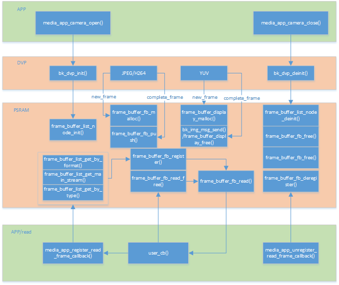
Figure 1. dvp process flow chart
Note
In this solution, all large memory uses PSRAM. Currently, the SRAM solution is not supported.
Adapting a New Camera
To adapt a new DVP camera, you need to add the corresponding DVP driver file to the peripheral files. This mainly includes the I2C configuration table for sensor registers, with different tables for different resolutions. The specific structure of the sensor is as follows:
// DVP camera structure
typedef struct
{
    char *name;  /**< Sensor name */
    media_ppi_t def_ppi;  /**< Sensor default resolution */
    frame_fps_t def_fps;  /**< Sensor default fps */
    mclk_freq_t  clk;  /**< Sensor working clock at the configured fps and ppi */
    pixel_format_t fmt; /**< Sensor output data format */
    sync_level_t vsync; /**< Sensor vsync active level  */
    sync_level_t hsync; /**< Sensor hsync active level  */
    uint16_t id;  /**< Sensor type, sensor_id_t */
    uint16_t address;  /**< Sensor write register address via I2C */
    uint16_t fps_cap;  /**< Sensor supported fps */
    uint16_t ppi_cap;  /**< Sensor supported resolutions */
    bool (*detect)(void);  /**< Auto-detect the used DVP sensor */
    int (*init)(void);  /**< Initialize the DVP sensor */
    int (*set_ppi)(media_ppi_t ppi);  /**< Set the resolution of the sensor */
    int (*set_fps)(frame_fps_t fps);  /**< Set the fps of the sensor */
    int (*power_down)(void);  /**< Power down or reset the sensor */
    int (*dump_register)(media_ppi_t ppi);  /**< Dump the sensor register */
    void (*read_register)(bool enable);  /**< Read the sensor register when writing */
} dvp_sensor_config_t;
- Explanation of some parameters:
clk: The input clock of the camera. The default value is 24MHz, which needs to be configured according to the camera specification.
fmt: The format of the data output by the camera to the chip. Currently, only YUV420 is supported. The order needs to be synchronized with the camera output order, with the default being YUYV.
vsync: The active level of the vsync output by the camera. For some cameras, valid data is output when vsync is low. It needs to be synchronized with the vsync output level of the camera, with the default being active high.
hsync: The active level of the hsync output by the camera. For some cameras, valid data is output when vsync is low. It needs to be synchronized with the hsync output level of the camera, with the default being active high.
address: The I2C slave address for configuring the camera registers, which needs to be configured according to the camera specification.
fps_cap: The list of frame rates supported by the camera, which needs to be implemented by configuring the corresponding registers.
ppi_cap: The list of resolutions supported by the camera, which needs to be implemented by configuring the corresponding registers.
Common Issues
This section mainly describes the common issues and solutions encountered during the debugging and use of DVP cameras.
Q: The camera cannot be recognized.
A: If the camera cannot be recognized, it indicates that there are errors in the parameter configuration in dvp_xxx.c for the newly adapted sensor. The most fundamental issues are the I2C read/write address and the CHIP_ID of the new sensor. If even the GC2145 cannot be recognized, check whether the sensor power supplies DVDD and IOVDD meet the protocol requirements, whether the GPIO for power control on the hardware is also GPIO28, and whether the I2C uses the corresponding GPIO0 and GPIO1. In addition, pay attention to contact issues, as loose physical connections may also cause malfunction.
Q: The image output is abnormal, and the message “sensor’s yuyv data resolution is not right” is printed.
A: This indicates that the DVP data collected by the main controller does not match the configured resolution. You can use a logic analyzer to capture the vsync/hsync/pclk signals. The following conditions must be met: If the resolution configured for the main controller is 640X480, then one vsync must contain 480 hsync pulses, and one hsync must contain 640*2 = 1280 pclk pulses. If these conditions are not met, the image output will definitely be abnormal. This problem may be caused by poor physical contact, and you need to re-plug and install the camera. It may also be due to the wire sequence being inconsistent with the default of BK7258, resulting in abnormal data collection. The pclk may be affected by the electromagnetic interference of the board, causing inaccurate sampling by the main controller. You can connect a pull-up filter capacitor of 8 - 22pf to the pclk.
Q: The image output is abnormal, and the message “sensor fifo is full” is printed.
A: This indicates that the main controller is receiving DVP data too slowly, causing the sensor FIFO to overflow. You can try the following solutions: Reduce the frame rate/reduce the resolution/increase the clock frequency of the YUV_BUF hardware module (currently, the default values are JPEG: : 120MHz, H264: 120MHz).
Q: The image output is abnormal, and the message “jpeg code rate is slow than sensor’s data rate” is printed.
A: This indicates that the encoding speed is too slow. You can try the following solutions: Reduce the frame rate/reduce the resolution/increase the clock frequency of the encoding hardware module (currently, the default values are JPEG: 120MHz, H264: 120MHz).
Q: The image output is abnormal, and the message “h264 encode erro” is printed.
A: This indicates an H264 encoding error. The possible reasons are that the frame gap time of the sensor is too short, causing the main controller to malfunction; It may also be that the previous frame has not been encoded before the start of the new H264 encoding. In this case, the software code has already covered this issue, and you can directly reset the relevant hardware modules.
Q: The I2C becomes abnormal after switching on and off, and the camera cannot communicate normally.
A: This situation usually occurs when other peripherals share the same I2C with the DVP, and the I2C is taken over by other peripherals. It is recommended to use software I2C to prevent malfunctions after sharing. Enable the software I2C function macro control:
marco
value
implication
CONFIG_SIM_I2C
Y
enable gpio simulate I2C function
Q: When configured in the H264/JPEG encoding mode, the abnormal message “··· size no match···” is printed.
A: In general, the length of the data transferred by DMA does not match the actual encoding length. In this case, the software will discard the wrong frame by default to prevent issues such as screen artifacts, and reset the corresponding module.
Q: The viewing angle is not in the center when the image is output.
A: This problem is caused by the configuration parameters (registers) of the DVP. It is recommended to ask the sensor manufacturer’s engineer to re - configure. Currently, the configuration provided by the SDK only ensures normal image output.