I2S User Guide
Overview
The I2S/PCM bus interface is a bidirectional 4-wire interface primarily used for audio data transmission. This interface can support various formats of I2S mode, such as Philips Left Justified、Right Justified; It can also support various formats of PCM mode, such as Short Sync, Long Sync, GCI, IDL, etc.
The BK I2S Driver supports following work modes:
- I2S (Philips)
In this working mode, the sequence diagram is shown in the sequence transmission as shown in
Figure 1:
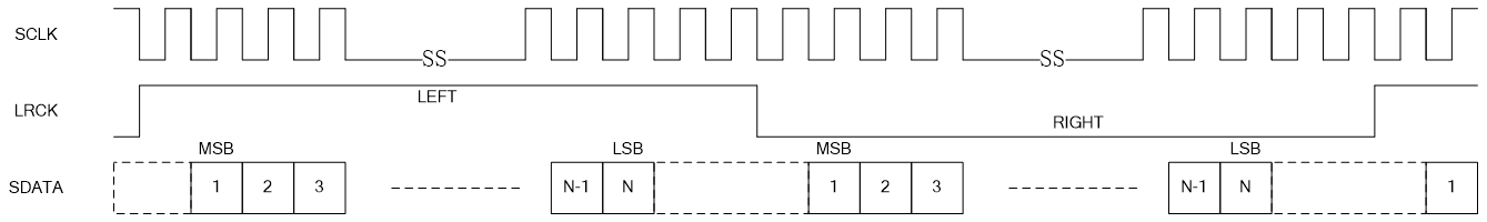
Figure 1. Philips mode time sequence diagram
- Left Justified
In this working mode, the sequence diagram is shown in the sequence transmission as shown in
Figure 2:
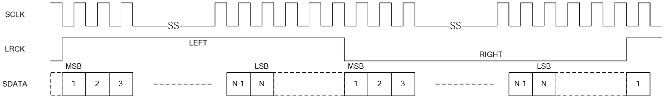
Figure 2. Left Justified mode time sequence diagram
- Right Justified
In this working mode, the sequence diagram is shown in the sequence transmission as shown in
Figure 3:
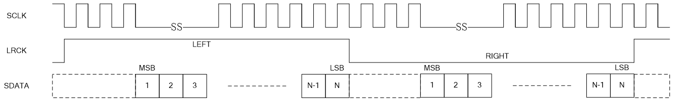
Figure 3. Right Justified mode time sequence diagram
- Short Frame Sync
In this working mode, the sequence diagram is shown in the sequence transmission as shown in
Figure 4:
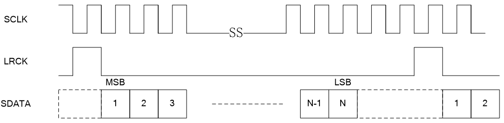
Figure 4. Short Frame Sync mode time sequence diagram
- Long Frame Sync
In this working mode, the sequence diagram is shown in the sequence transmission as shown in
Figure 5:
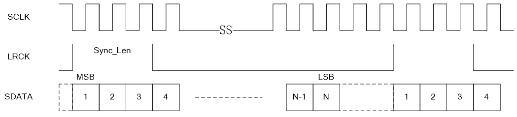
Figure 5. Long Frame Sync mode time sequence diagram
- Normal 2B+D
In this working mode, the sequence diagram is shown in the sequence transmission as shown in
Figure 6 and Figure 7:
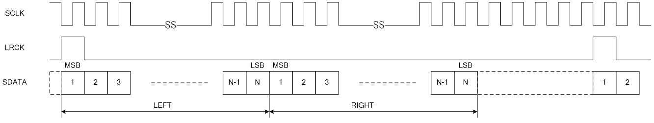
Figure 6. Normal 2B+D mode time sequence diagram
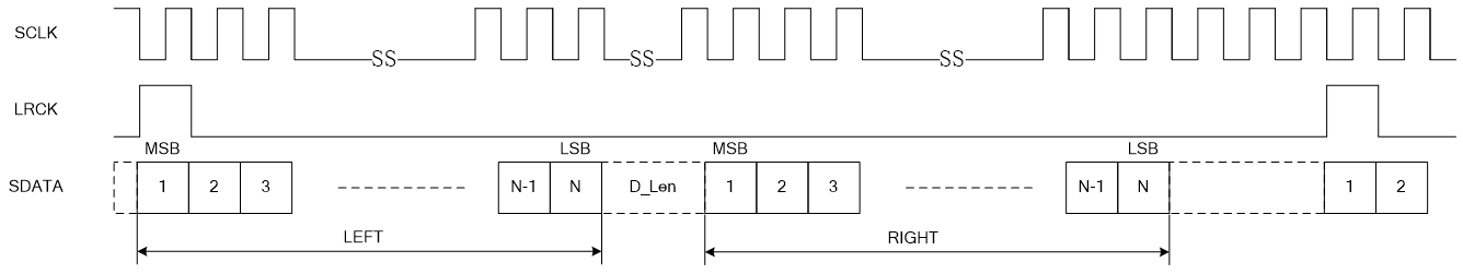
Figure 7. Normal 2B+D mode time sequence diagram
- Delay 2B+D
In this working mode, the sequence diagram is shown in the sequence transmission as shown in
Figure 8 and Figure 9:
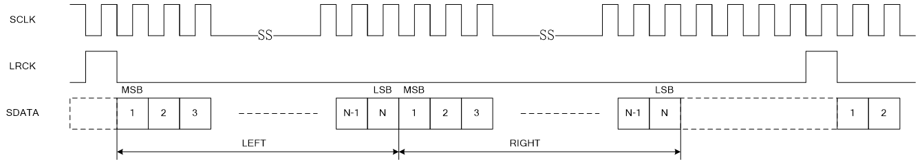
Figure 8. Delay 2B+D mode time sequence diagram
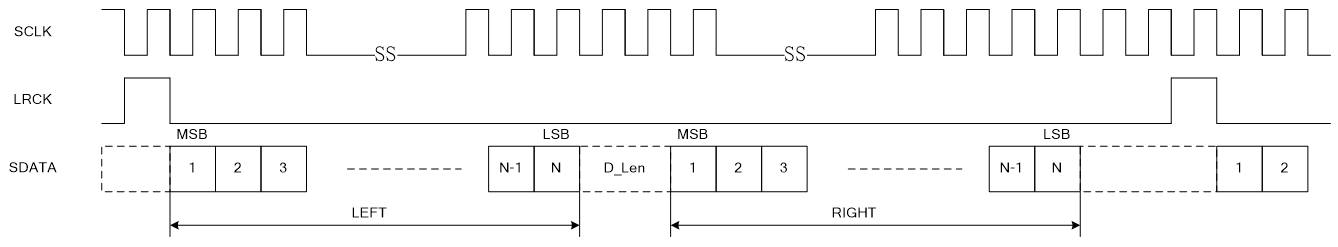
Figure 9. Delay 2B+D mode time sequence diagram
Hardware connection
The pin descriptions for I2S communication are as follows:
GPIO |
in/out |
introduce |
|---|---|---|
SCLK |
in&out |
The clock signal for I2S operation, also known as BCLK |
LRCK |
in&out |
Left and right channel clock, also known as WS (sync clock in PCM) |
DIN |
in |
Data input pin |
DOUT |
out |
Data output pin |
BK7258 has three I2S channels, and the GPIO pins for each I2S channel are shown in the table below:
GPIO |
Group 0 |
Group 1 |
Group 2 |
|---|---|---|---|
SCLK |
GPIO_6 |
GPIO_40 |
GPIO_44 |
LRCK |
GPIO_7 |
GPIO_41 |
GPIO_45 |
DIN |
GPIO_8 |
GPIO_42 |
GPIO_46 |
DOUT |
GPIO_9 |
GPIO_43 |
GPIO_47 |
BK7258 has one or more channels for data transmission and reception under each I2S channel. The channel information is shown in the table below:
Group |
Number of channels |
|---|---|
Group 0 |
3 |
Group 1 |
1 |
Group 2 |
1 |
Important
In general, one channel can meet the needs of an application, and multiple channels are mainly used in Time Division Mode (DTM).
I2S debugging precautions
When communicating with I2S, the two devices are respectively ‘master’ and ‘slave’, and ‘SCLK’ and ‘LRCK’ are provided by ‘master’.
Before calling the interface, it is necessary to confirm the device’s role, working mode, sampling rate, number of channels, bit width, data transmission order, data storage format, and other information. Based on this information, configure I2S.
For the four typical working modes of I2S, the driver provides default configurations, which can be adjusted based on actual applications.
The configuration of the slave needs to be consistent with the master. If the working mode of the master is uncertain, the pin waveform of the master can be analyzed by grabbing it through a logic analyzer.
Instructions for using the I2S interface
The usage process of I2S interface is as follows:
Call the
bk_i2s_driver_itinterface to initialize the driver of I2SCall the
bk_i2s_itinterface to initialize and configure the selected I2S GroupCall the
bk_i2s_chl_itinterface to initialize the specified channelCall the
bk_i2s_startinterface to initiate I2S communicationSend pending data to the channel or read received data in the callback function registered in the channel
Next, taking the transmission and reception in I2S mode as an example, a detailed explanation of the interface configuration and usage will be provided.
The host works in I2S mode and sends data as an example:
/* Create a TX callback for the channel and continuously send fixed data to the channel during the callback */
static int ch1_tx_data_handle_cb(uint32_t size)
{
        ring_buffer_write(ch1_tx_rb, ch1_temp, size);

        return size;
}

/* Using default I2S configuration */
i2s_config_t i2s_config = DEFAULT_I2S_CONFIG();
bk_err_t ret = BK_OK;
uint32_t size = 0;

uint8_t *ch1_temp = os_malloc(320);
os_memset(ch1_temp, 0xF1, 320);

//init i2s driver
bk_i2s_driver_init();

//init i2s configure
i2s_config.samp_rate = I2S_SAMP_RATE_48000;
bk_i2s_init(I2S_GPIO_GROUP_2, &i2s_config);
os_printf("init i2s driver and config successful \r\n");

/* Configure the first channel for sending data, with a data size of (640/2) bytes per frame */
ret = bk_i2s_chl_init(I2S_CHANNEL_1, I2S_TXRX_TYPE_TX, 640, ch1_tx_data_handle_cb, &ch1_tx_rb);
if (ret != BK_OK) {
        os_printf("bk_i2s_chl_init fail \n");
        return;
}

uint8_t *temp_data = (uint8_t *)os_malloc(640);
os_memset(temp_data, 0x00, 640);
/* Fill the channel with data before starting to send */
size = ring_buffer_write(ch1_tx_rb, temp_data, 640);
os_printf("ring_buffer_write, size: %d \n", size);
os_free(temp_data);
/* Start I2S to start sending data */
bk_i2s_start();
The configuration information of I2S is as follows:
    #define DEFAULT_I2S_CONFIG() {                     \
    .role = I2S_ROLE_MASTER,                       \
    .work_mode = I2S_WORK_MODE_I2S,                \
    .lrck_invert = I2S_LRCK_INVERT_DISABLE,        \
    .sck_invert = I2S_SCK_INVERT_DISABLE,          \
    .lsb_first_en = I2S_LSB_FIRST_DISABLE,         \
    .sync_length = 0,                              \
    .data_length = 16,                             \
    .pcm_dlength = 0,                              \
    .store_mode = I2S_LRCOM_STORE_LRLR,            \
    .samp_rate = I2S_SAMP_RATE_8000,               \
    .pcm_chl_num = 2,                              \
}
Note
lrck_invertis used to configure whether theLRCKsignal is reversed (only valid in I2S operating mode for transmitting dual channel data). By default, the low level ofLRCKrepresents the right channel, and the high level represents the left channel.sck_invertis used to configure whether theSLCKsignal is reversed. By default, the input data is sampled on the rising edge ofSCLK, and the output data changes on the falling edge ofSCLK.lsd_first_enis used to configure the timing of data transmission. If enabled, the low bit is sent first and then the high bit. By default, the high bit is sent first and then the low bit.sync_lengthis used to configure the number of bits for synchronization (only valid in PCM operating mode), can be ignored in I2S mode.data_lengthis used to configure the number of bits for mono data, please note that it is the number of bits for mono.pcm_lengthis used to configure the number of digits for PCM data (only valid in PCM operating mode), which can be ignored in I2S mode.store_modeis used to configure the storage mode of data within the channel, I2S-LRCOM-STORE16R16L: Left and right channel data are combined into a 32bit file and written into PCM-DAT simultaneously. The low 16bit file corresponds to the left channel, and the high 16bit file corresponds to the right channel, i.e {R,L}- > {R,L}- >This mode can only be configured when the data length is less than 16. I2S-LRCOM-STORE.LRLR: The left and right channel data are alternately written into PCM-DAT in chronological order, that is, L ->R ->L ->R ->.
The example of receiving and transmitting data from the slave operating in I2S mode is as follows:
/* Create an RX callback for the channel and continuously read the data received by the channel during the callback */
static int ch1_rx_data_handle_cb(uint32_t size)
{
        //os_printf("%s, size: %d \n", __func__, size);
        ring_buffer_read(ch1_rx_rb, ch1_temp, size);
        os_printf("rx ch1_temp[0]: 0x%2x \n", ch1_temp[0]);

        return size;
}


/* Using default I2S configuration */
i2s_config_t i2s_config = DEFAULT_I2S_CONFIG();
bk_err_t ret = BK_OK;
uint32_t size = 0;

uint8_t *ch1_temp = os_malloc(320);
os_memset(ch1_temp, 0xF1, 320);

//init i2s driver
bk_i2s_driver_init();

//init i2s configure
i2s_config.role = I2S_ROLE_SLAVE;
i2s_config.samp_rate = I2S_SAMP_RATE_48000;
bk_i2s_init(I2S_GPIO_GROUP_0, &i2s_config);
os_printf("init i2s driver and config successful \r\n");

/* Configure the first channel for receiving data, with a data size of (640/2) bytes per frame */
ret = bk_i2s_chl_init(I2S_CHANNEL_1, I2S_TXRX_TYPE_RX, 640, ch1_rx_data_handle_cb, &ch1_rx_rb);
if (ret != BK_OK) {
        os_printf("bk_i2s_chl_init fail \n");
        return;
}

/* Start I2S to receive data */
bk_i2s_start();
Reference link
API Reference : Introduced the I2S API interface
User and Developer Guide : Introduced common usage scenarios of I2S
Samples and Demos: Introduced the use and operation of I2S samples