GPIO User Guide
Overview
The GPIO (General Purpose Input/Output) module is a core module on the chip used for signal communication with external devices. The BK7258 chip has 56 general-purpose input/output pins (GPIO Pins), each of which can be used as a general-purpose IO or connected to an internal peripheral signal.
GPIO MAP Config
gpio_map.h
GPIO is configured according to the MAP(GPIO_DEFAULT_DEV_CONFIG) during driver initialization of each CPU core. Each row in the map contains nine elements. The 11 elements are as follows:
gpio_id:Corresponding PIN number starting from 0
second_func_en:Whether to enable the secondary function.
second_func_dev:Select the second function of the PIN.(Currently, a single GPIO PIN can reuse up to eight secondary functions. see GPIO_DEV_MAP. This table cannont be modified bu user)
io_mode:Select the IO operating mode, input\output\high resistance.(In output mode,it is an open-drain output)
pull_mode:Select IO level pull up or pull down
int_en:Whether to turn on interrupt
int_type:Select trigger interrupt condition, high\low\rise\fall.
low_power_io_ctrl:Low power whether to maintain the output level(Configuring GPIO_LOW_POWER_KEEP_INPUT_STATUS can set the GPIO as a wake-up source. If it is set as a wake-up source, you need to enable the interrupt and configure the interrupt type. If this bit is not set, the GPIO will be in high resistance when entering low power mode).
driver_capacity:Driver ability selection, a total of four levels.
gpio_init: During power-on initialization, does it operate GPIO according to the configuration of GPIO_DEFAULT_DEV_CONFIG
gpio_time_sharing_multiplex: GPIO time-sharing multiplexing flag.(enable: Allows dynamic mapping/unmapping of GPIO, enabling the ability to dynamically configure the secondary function of GPIO. disable: Disallows dynamic configuration of GPIO’s secondary function. If GPIO has a time-sharing multiplexing requirement, the gpio_time_sharing_multiplex field must be enabled).
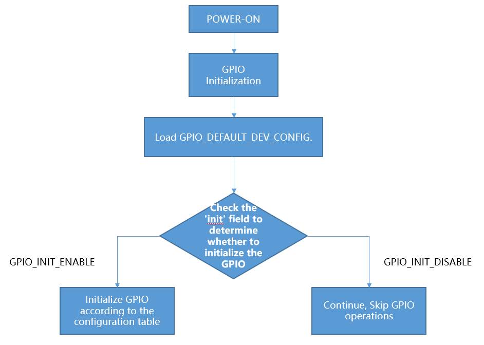
gpio_initialization
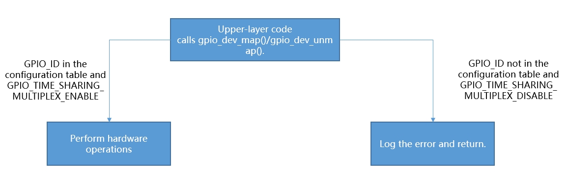
upper_call_map.png
GPIO partial usage introduction:
When creating a new project,Customers need to configure the GPIO_DEFAULT_DEV_CONFIG table according to their board configuration requirements.You can freely configure the GPIO_DEFAULT_DEV_CONFIG table according to the capabilities of each GPIO defined in the GPIO_DEV_MAP table. When initializing GPIO peripherals in the gpio_hal.c file, the gpio_hal_default_map_init() function initializes GPIO according to the GPIO_DEFAULT_DEV_CONFIG table during the first initialization (only if the macro CONFIG_GPIO_DEFAULT_SET_SUPPORT is enabled). If this macro is not enabled, the platform will not operate the GPIO, and the default state of GPIO will be set to a high resistance.
override the default GPIO_DEFAULT_DEV_CONFIG in a customized way, follow the steps below:
Open macro definition: Open the CONFIG_USR_GPIO_CFG_EN macro in your project configuration file to enable the custom GPIO configuration function.
Create the usr_gpio_cfg.h file: Create the usr_gpio_cfg.h header file in an appropriate location in your project and define your custom GPIO_DEFAULT_DEV_CONFIG in this file. This configuration should contain the initialization settings and mappings for all GPIOs you want. For example, You can add usr_gpio_cfg.h header file to the ‘bk_avdk_smp_release\projects\app\config\bk7258’.
It should be noted that the newly mapped function must have been defined in the GPIO_DEV_MAP table. During initialization, the chip will configure the GPIO status according to the GPIO_DEFAULT_DEV_CONFIG table.(note:Make sure to include the usr_gpio_cfg.h file in your code so that your custom GPIO configuration is used when compiling.)
Low power state: Can be configured as input mode and output mode. If the corresponding GPIO (GPIO_LOW_POWER_DISCARD_IO_STATUS) is not used during low power , the low power mode program will set the GPIO to a high resistance state to prevent leakage during low power mode.
maintain the output state of GPIO in low-power mode, there are two methods to configure:
Configure the GPIO_DEFAULT_DEV_CONFIG table according to the instructions.
Use the bk_gpio_register_lowpower_keep_status() function to register. The default number is 4, which can be modified using CONFIG_GPIO_DYNAMIC_KEEP_STATUS_MAX_CNT.
Use the bk_gpio_unregister_lowpower_keep_status() function to cancel the registration of GPIOs that need to maintain their status.
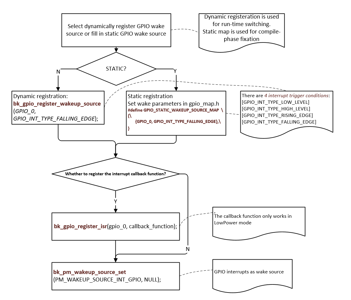
When entering low-power mode, multiple external GPIOs can be set as wake-up sources. If any of these GPIOs generates an interrupt signal, the chip can wake up from low-power mode. There are currently three methods to configure wake-up sources:
Configure according to the instructions in the GPIO_DEFAULT_DEV_CONFIG table.
Set multiple wake-up sources in the GPIO_STATIC_WAKEUP_SOURCE_MAP.
Register wake-up sources using the bk_gpio_register_wakeup_source() function. (The default number is 4, but it can be modified using CONFIG_GPIO_DYNAMIC_WAKEUP_SOURCE_MAX_CNT).
Use the bk_gpio_unregister_wakeup_source() function to cancel the registration of wake-up sources.
When entering low power mode(Low voltage only), the status of GPIO will be backed up. After exiting, GPIO will be automatically restored to the state before entering low power mode. (note:After exiting from deep sleep mode, it is equivalent to a soft restart, and the GPIO status will not be automatically restored.If necessary to exit from deep sleep mode and maintain the GPIO status, see point 8.)
To maintain GPIO states during software restarts:
Set the gpio_init field corresponding to GPIO_ID to disable
When setting up input interrupt detection, it is essential to ensure the signal level is stable before enabling the interrupt. The handling logic is as follows: first, clamp the signal level to either a high level or a low level (depending on the interrupt trigger mode). For instance, if the interrupt is triggered by a rising edge, the GPIO should be initially set to a low state to prevent jitter or random high resistance values from causing unintended triggers.
CP and AP must configure their own GPIO, and the same GPIO cannot be configured repeatedly on both CP and AP.
GPIOs that are not explicitly assigned cannot be mapped/unmapped, are defaulted to a high impedance state, and can only be used as GPIOs.
The SDK has integrated the key component, which allows users to quickly implement key detection functionality through this component. The key component is located at
ap\components\key. For usage, refer to the example code inap\components\bk_cli\cli_key.c.
Note
usr_gpio_cfg.h must be configured.
When GPIO is set to level-triggered interrupt mode, if the valid level of the detected pin persists, it will cause the interrupt to be triggered repeatedly.
- The driving capacity of GPIO is shown in the table below. REG indicates the set value of the GPIO register, there are four levels for drive capability.
REG=2
REG=102
REG=202
REG=302
P14
10.49
19.95
33.72
40.8
P15
10.48
19.9
33.28
40.03
P16
10.41
19.65
32.76
39.35
P17
10.36
19.45
32.26
38.6
High level pull current(mA)
REG=0
REG=100
REG=200
REG=300
P14
8.54
16.09
26.05
32
P15
8.56
16.19
26.47
32.6
P16
8.56
16.35
26.87
33.24
P17
8.62
16.5
27.24
33.85
Low level-sink current(mA)
Example:
- Configure GPIO_0 to function [GPIO_DEV_I2C1_SCL] and GPIO_1 to function [GPIO_DEV_I2C1_SDA]:
gpio_id
second_func_en
second_func_dev
io_mode
pull_mode
int_en
int_type
low_power_io_ctrl
driver_capacity
gpio_init
gpio_time_sharing_multiplex
GPIO_0
GPIO_SECOND_FUNC_ENABLE
GPIO_DEV_I2C1_SCL
GPIO_IO_DISABLE
GPIO_PULL_UP_EN
GPIO_INT_DISABLE
GPIO_INT_TYPE_LOW_LEVEL
GPIO_LOW_POWER_DISCARD_IO_STATUS
GPIO_DRIVER_CAPACITY_3
GPIO_INIT_ENABLE
GPIO_TIME_SHARING_MULTIPLEX_DISABLE
GPIO_1
GPIO_SECOND_FUNC_ENABLE
GPIO_DEV_I2C1_SDA
GPIO_IO_DISABLE
GPIO_PULL_UP_EN
GPIO_INT_DISABLE
GPIO_INT_TYPE_LOW_LEVEL
GPIO_LOW_POWER_DISCARD_IO_STATUS
GPIO_DRIVER_CAPACITY_3
GPIO_INIT_ENABLE
GPIO_TIME_SHARING_MULTIPLEX_DISABLE
PS:GPIO is turned off by default when the second function is used (io_mode is [GPIO_IO_DISABLE]). I2C needs more driving capability (driver_capacity is [GPIO_DRIVER_CAPACITY_3]).
- GPIO_0 is set to high resistance(Default state):
gpio_id
second_func_en
second_func_dev
io_mode
pull_mode
int_en
int_type
low_power_io_ctrl
driver_capacity
gpio_init
gpio_time_sharing_multiplex
GPIO_0
GPIO_SECOND_FUNC_DISABLE
GPIO_DEV_INVALID
GPIO_IO_DISABLE
GPIO_PULL_DISABLE
GPIO_INT_DISABLE
GPIO_INT_TYPE_LOW_LEVEL
GPIO_LOW_POWER_DISCARD_IO_STATUS
GPIO_DRIVER_CAPACITY_0
GPIO_INIT_DISABLE
GPIO_TIME_SHARING_MULTIPLEX_DISABLE
PS:Disable all config
- GPIO_0 is set to input key and falling edge to trigger the interrupt:
gpio_id
second_func_en
second_func_dev
io_mode
pull_mode
int_en
int_type
low_power_io_ctrl
driver_capacity
gpio_init
gpio_time_sharing_multiplex
GPIO_0
GPIO_SECOND_FUNC_DISABLE
GPIO_DEV_INVALID
GPIO_INPUT_ENABLE
GPIO_PULL_UP_EN
GPIO_INT_ENABLE
GPIO_INT_TYPE_FALLING_EDGE
GPIO_LOW_POWER_DISCARD_IO_STATUS
GPIO_DRIVER_CAPACITY_0
GPIO_INIT_ENABLE
GPIO_TIME_SHARING_MULTIPLEX_DISABLE
PS:Turn off the second function related. There are 4 interrupt trigger conditions:[GPIO_INT_TYPE_LOW_LEVEL],[GPIO_INT_TYPE_HIGH_LEVEL],[GPIO_INT_TYPE_RISING_EDGE],[GPIO_INT_TYPE_FALLING_EDGE].
- GPIO_0 acts as a low power wake-up source, Falling edge wake-up:
gpio_id
second_func_en
second_func_dev
io_mode
pull_mode
int_en
int_type
low_power_io_ctrl
driver_capacity
gpio_init
gpio_time_sharing_multiplex
GPIO_0
GPIO_SECOND_FUNC_DISABLE
GPIO_DEV_INVALID
GPIO_INPUT_ENABLE
GPIO_PULL_UP_EN
GPIO_INT_ENABLE
GPIO_INT_TYPE_FALLING_EDGE
GPIO_LOW_POWER_KEEP_INPUT_STATUS
GPIO_DRIVER_CAPACITY_0
GPIO_INIT_ENABLE
GPIO_TIME_SHARING_MULTIPLEX_DISABLE
PS:low_power_io_ctrl is [GPIO_LOW_POWER_KEEP_INPUT_STATUS].
Q&A
In low-power mode, both the RTC and GPIO interrupts are configured. However, after the RTC triggers, the GPIO functionality becomes ineffective.
This issue arises because, before entering low-power mode, the MCU backs up the states of the GPIOs. To prevent the MCU from failing to wake up due to the lack of enabled wake-up GPIO pin interrupts, the wake-up GPIO pin interrupts are enabled in low-power mode. Upon exiting the interrupt, the state of that pin is restored to what it was before entering low-power mode. If the wake-up pin interrupt was not enabled before entering low-power mode, it remains disabled after exiting low-power mode. Consequently, the wake-up GPIO interrupt cannot be triggered in normal operating mode.
After entering deep sleep mode, tapping on the UART can wake up the device.
Because of the needs of some secondarios,the default supports for using the UART to wake up the device, if you don’t need this function, You can comment out GPIO_10 in the GPIO_STATIC_WAKEUP_SOURCE_MAP section of the gpio_map.h file.
Coordination issues between multi-core operations and the same GPIO, A customer in a multi-core system did not adopt a CPU-independent GPIO configuration scheme, resulting in the following typical issues, manifested as:
After enabling the DVP camera, the key interrupt is occasionally lost.
When only LCD or UVC is enabled, the key GPIO interrupt does not trigger approximately 50% of the time.
All GPIO pins share a common GPIO interrupt line. If each CPU does not configure its own required GPIO, an interrupt on any GPIO pin will trigger all CPUs to receive the interrupt notification and execute the interrupt handling function.Enabling peripherals such as DVP and LCD can start up CPU1, which operates at a higher frequency than CPU0. This higher frequency might inadvertently clear interrupt flag bits, leading to lost GPIO interrupts on CPU0. To prevent this, it is essential that each CPU configures its own GPIO map table individually.
Application Example
- DEMO1:
GPIO_0 as wake-up source for DeepSleep or LowPower, pseudo code description and interpretation.
GPIO as wake-up source for DeepSleep or LowPower