This project is based on an end-to-cloud, cloud-to-large-model design solution.
Supports dual-screen display, providing visual and voice companionship experience and emotional value.
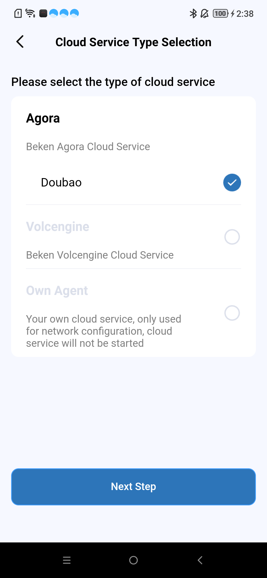
Supports end-side integration with various general large model design solutions, directly connecting to Open AI, Doubao, DeepSeek, etc.
And can effectively utilize cloud distributed deployment to reduce network latency and improve interaction experience.
Supports end-side AEC, NS and other audio processing algorithms, supports G711/G722 encoding formats, supports KWS keyword interruption wake-up, supports prompt tone playback.
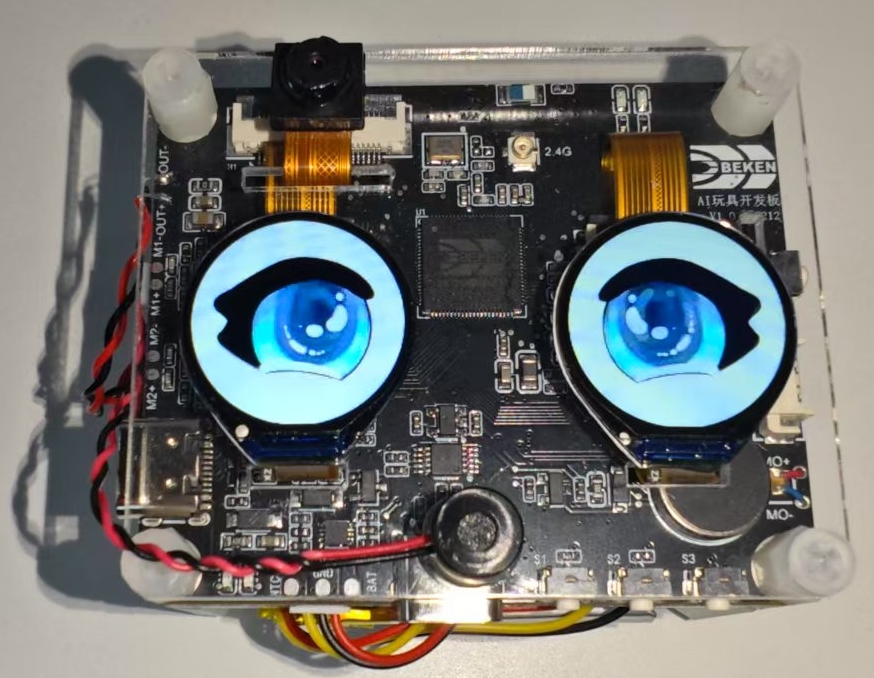
Includes reference designs and demos for common peripherals, such as gyroscope, NFC, buttons, vibration motor, Nand Flash, LED effects, charging management, DVP camera, dual QPSI screens.
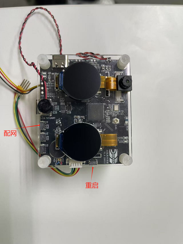
There are red and green status indicator lights on the top of the development board. Important information is indicated by red light blinking, general prompts by green light blinking, and special reminders by red and green lights alternating blinking.
Green Light Always On/Off Prompt Information
When powering on, green light stays on, waiting for user operation or next event to start
When conversation starts, green light turns off
Red and Green Lights Alternating Blink Prompt Information
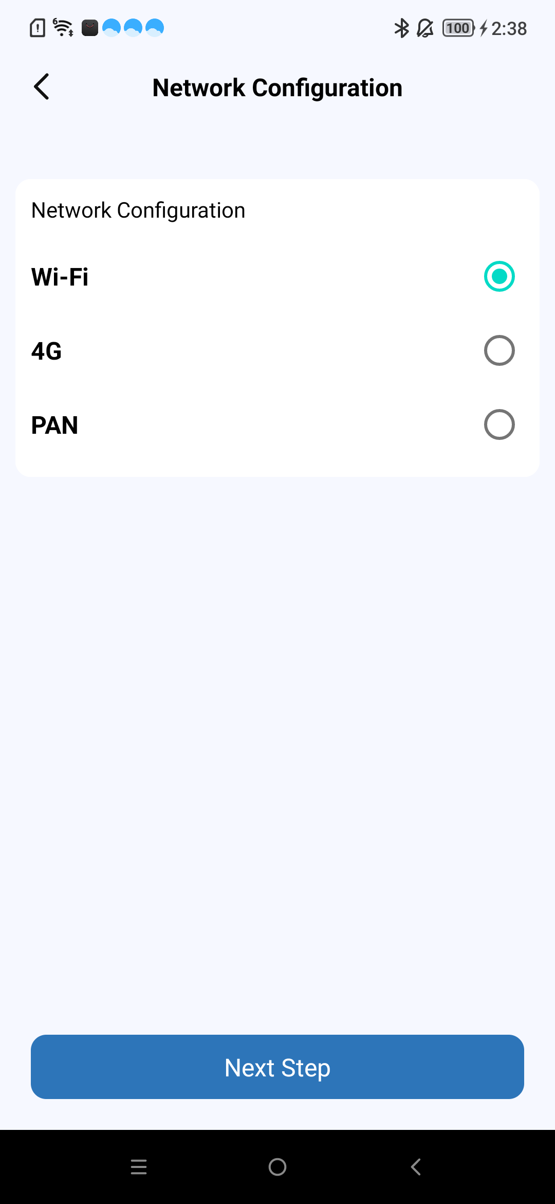
User Network Provisioning: User network provisioning
Green Light Blink Prompt Information
Power-on Network Connecting: Green light fast blink
Large Model Server Connection Success: Green light slow blink
Conversation Stopped: Green light slow blink
Red Light Blink Prompt Information
Network Provisioning Failure/Network Reconnection Failure: Red light fast blink
RTC Connection Disconnected: Red light fast blink
Large Model Server Connection Disconnected: Red light fast blink
Battery Level Below 20%: Red light slow blink for 30 seconds then automatically stops blinking; if charging, red light does not blink
No Important Reminder Events: When there are no important reminder events, red light is in off state
LED effect development reference code: led_blink.c.
The current development board uses charging management chip model (ETA3422)
When fully charged, the red light next to the charging port will turn off and green light will turn on; red light on indicates charging
Note: During charging or when external power is connected, the system switches to external input voltage source for voltage detection instead of using battery voltage. At this time, the voltage obtained by command is the external input voltage.
Charging status monitoring depends on GPIO51 and GPIO26. GPIO51 indicates external power (high = present). GPIO26 indicates charging (high) or full (low). Note: R14 must be soldered for this function. Hardware details follow the project schematic.
To enable charging management function, configure CONFIG_BAT_MONITOR=y. To enable charging management test cases, configure CONFIG_BATTERY_TEST=y.
After enabling battery test command configuration, battery information can be obtained through the battery CLI. Examples: batteryinit; batteryget_battery_info; batteryget_voltage; batteryget_level. On external power, reported voltage reflects the supply. Send battery for more commands; see cli_battery.c.
When battery level is equal to or less than 20%, a low battery warning is sent only when not plugged in, once per low-battery entry; the red indicator slow-blinks for 30s.
The charging management task will print “Device is charging…” information when charging.
When fully charged, it will print “Battery is full.” information.
Although the battery has low voltage protection function, it is recommended that users charge in time when battery is low to extend battery life.
If users use batteries from other manufacturers, they need to modify the battery level lookup table s_chargeLUT and battery basic information content in iot_battery_open according to specific battery information.
In our SDK, we provide API functions for current, voltage, and battery level. Currently, the battery only supports voltage and battery level detection functions. It should be noted that although the current detection API interface is reserved, it is not yet implemented. Therefore, if the user’s device supports current detection, the current API needs to be implemented by the user.
Since the current hardware only supports battery level detection in non-charging state, if users need to detect voltage during charging, hardware modification is required. Remove D6 diode and R21 resistor.
The USB port next to the key is both a charging port and a serial port.
The ADC interface for battery level sampling is the internal ADC0 of the chip. External resistor voltage divider circuit plus ADC channel acquisition is not required. ADC0 is directly connected to the VBAT monitoring channel. This interface is a dedicated internal interface of the chip with no external connections.
Note: The maximum battery detection voltage is 4.35V. Voltages above this may risk burning the system.
LDO is connected to the positive pole of the motor, PWM is connected to the negative pole of the motor. The vibration strength of the motor is controlled by adjusting the PWM duty cycle.
When powering on by long pressing the key, the motor will vibrate.
The development board plays corresponding prompt tones during operation based on different events. Below are the prompt tones associated with each event:
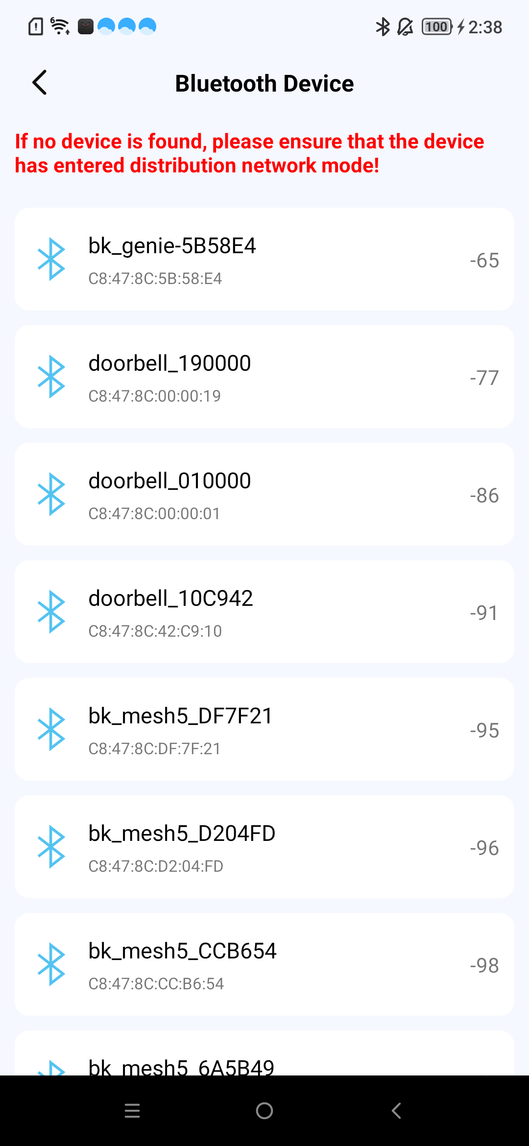
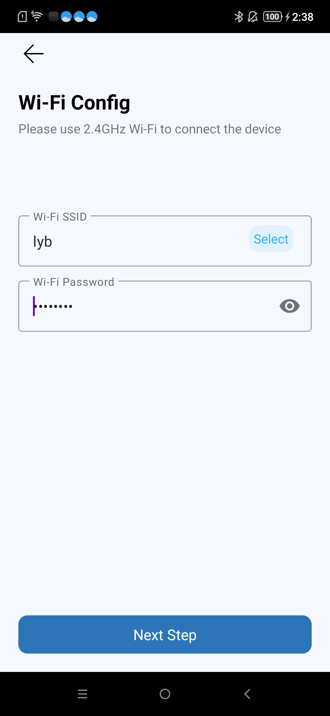
Provision network Over Bluetooth LE
1.Provision Network Over Bluetooth LE: PleaseuseBluetoothLEfornetworkprovision
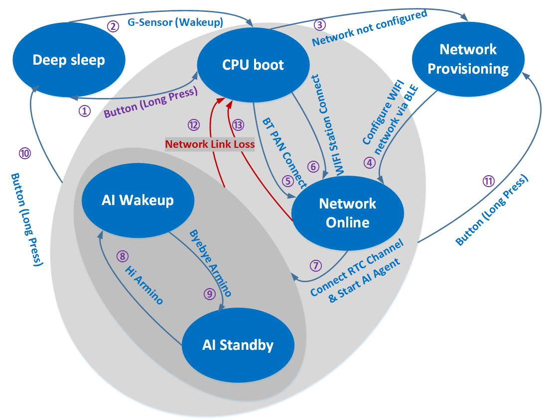
Network provisioning event countdown is 5 minutes. If not provisioned within 5 minutes, the chip will enter deep sleep (similar to power off).
Network error countdown is 5 minutes. If network error occurs and network is not restored within 5 minutes, the chip will enter deep sleep.
Standby state countdown is 3 minutes. The default state after system power-on is standby state. After you say byebyearmino or 拜拜阿米诺, the system will also be in standby state. If no other events occur, the chip will enter deep sleep after 3 minutes.
You can modify the countdown time in the s_ticket_durations[COUNTDOWN_TICKET_MAX] array in countdown_app.c.
Copy audio and video files from <armino_sdk_resource>/bk_avdk_smp/ap/components/ai_audio_engine/resource/ directory to SD NAND of AIDK development board.
For specific usage of SD NAND, please refer to Nand Disk Usage Notes
Say the wake-up word hiarmino to the onboard mic, the device will play the prompt tone aha after waking up,
and then you can have an AI conversation
Say the key word byebyearmino to the onboard mic, the device will play the prompt tone byebye after detecting it,
then go to sleep and stop talking to the AI
This AI demo solution is similar to the door lock solution. The device side and AI large model side have bidirectional voice calls, while the device side sends one-way image transmission to the AI large model side. The peer APK in the door lock solution becomes an AI Agent robot.
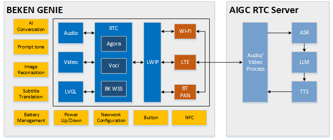
The software module architecture is shown in the following figure:
In the solution, the device side captures mic voice and sends voice data to the server through VolcEngine RTC SDK. The server is responsible for interaction with AI Agent large model, sends mic voice to AI Agent and gets reply, then sends voice reply to device side speaker for playback.
In the solution, the device side captures images and sends each frame image to the server through VolcEngine RTC SDK. The server then sends the image to AI Agent large model for recognition.
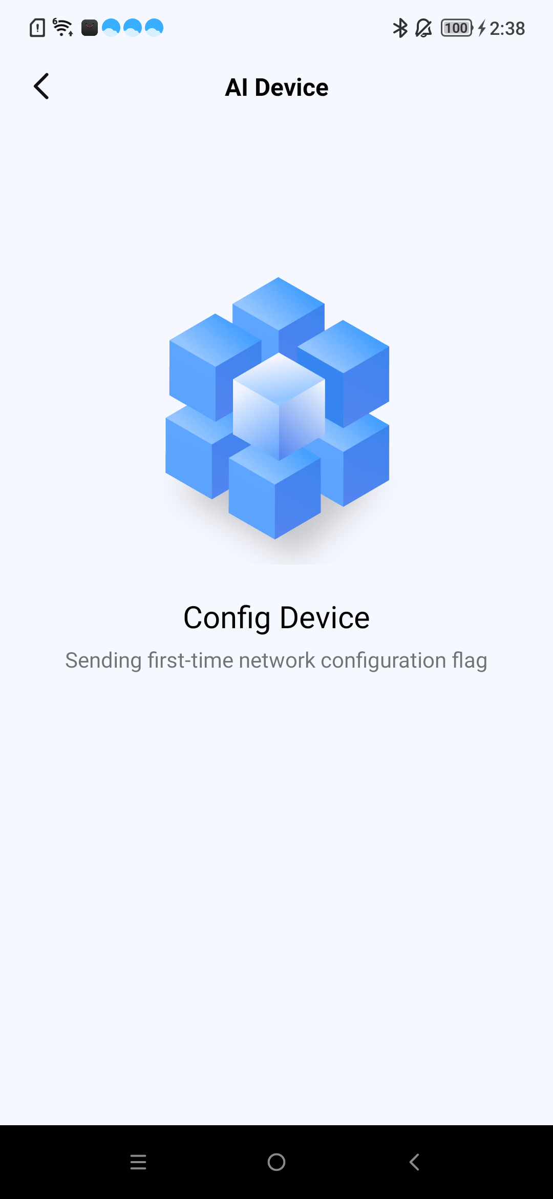
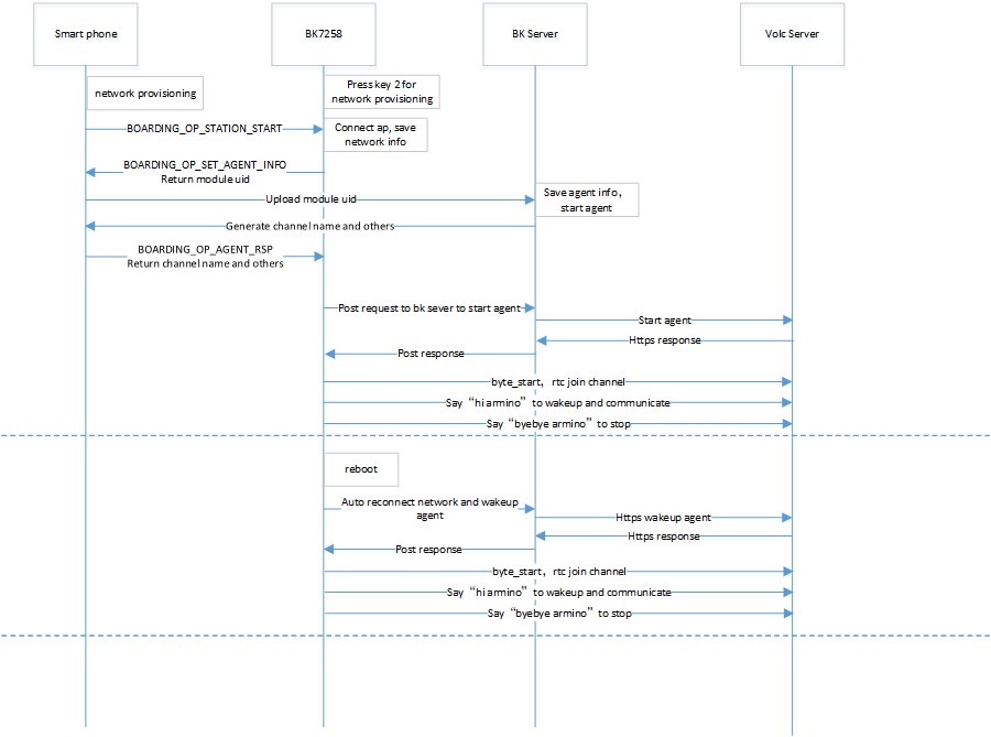
3.2 Network Provisioning and Conversation Sequence Diagram
Key function configuration, refer to /components/bk_key_app/key_app_config.h and key_app_service.c. Developers can fill in the corresponding IO pins and key callback function events in this table
Long key press duration configuration refers to LONG_TICKS macro definition in multi_button.h
Currently all key events are transferred to tasks for execution. If key event execution program is blocked or execution time is too long, it will affect key response speed
GPIO Key Notes
Please confirm that GPIO pins are only used for keys, otherwise GPIO pin function conflicts will cause key invalidation problems
If the developer’s development board is different from the beken_genie development board, please reconfigure GPIO according to the development board hardware design. For GPIO usage methods, please refer to bk_avdk_smp/ap/docs/bk7258/zh_CN/api-reference/peripheral/bk_gpio.rst
3.6 BLE Network Provisioning and Agent Customization Guide
BLE network provisioning and agent related code is mainly distributed in components/bk_smart_config directory. Customers can refer to the following instructions to customize their own solutions
Start Agent and RTC, refer to code bk_sconf_start_network_transfer(char*device_id)
This function will call the corresponding startup function based on the configured RTC backend (Agora or VolcEngine). For VolcEngine, it will call bk_byte_start(void*device_id), which will start both Agent and RTC.
After WiFi connection, start agent, save WiFi and agent information and network provisioning, refer to code bk_sconf_network_provisioning_status_cb(bk_network_provisioning_status_tstatus,void*user_data)
Q: Application layer has no mic data reporting?
A: Currently beken_genie supports voice wake-up function based on command words by default. Only after wake-up will mic captured data be reported to the application layer, and the application layer then sends data to AI for conversation. If customers do not need voice wake-up function, they can disable this function through macro CONFIG_AE_SUPPORT_PROMPT_TONE.
Q: UI resource playback display abnormal?
A: UI resources used in this project must be AVI format videos with resolution of 320x160, and must be converted using AVI conversion tool before use. You can first check whether UI resources meet the above requirements.