DOORBELL

[中文]

1 Overview

The main function of the doorbell is the joint module, real-time image acquisition, display screen, sound acquisition and communication.

2 Code Path

The path of demos: ./components/media/cli/media_cli.c``, ./components/media/camera/camera_act.c, ./components/media/transfer/transfer_act.c, ./components/media/lcd/lcd_act.c

3 Client command

The commands support by doorbell

Command

Param

Description

ap param1 param2

param1:softap_ssid

setup a softap and set name

param2:softap_key

set softap connect key

sta param1 param2

param1:station_ssid

connect a station and set name

param2:station_key

set station connect key

doorbell param1 [param2]

param1:3

open doorbell function

param2:if open uvc, choosable

set open/disopen uvc 1/0

media dvp open [param]

param:dvp resolution, choosable

set sensor resolution, and open dvp

media dvp close

NULL

close dvp sensor

media lcd open [param1] [param2]

param1:LCD PIXEL

default:480X272

param2:rotate or null

rotate open or not

media lcd close

NULL

close lcd function, and jpeg decode

media lcd dma2d_blend [param1][param2]

param1:clock,wifi,data,ver

blend icon type

param2:12:30 , 0-4

0:wifi none, 4:wifi full

media lcd dma2d_blend close [param]

NULL or wifi/clock

close all blend or one blend

media capture param

param:xxx.jpg

capture save to sdcard, and set name

media uvc open [param]

param:uvc resolution, choosable

set sensor resolution, and open uvc

media uvc close

NULL

close uvc sensor

The macro configuration that the demo runs depends on:

NAME

Description

File

value

CONFIG_DOORBELL

support DOORBELL

middleware\soc\bk7256\bk7256.defconfig

y

CONFIG_JPEG_ENCODE

suport hw jpeg ecoder

middleware\soc\bk7256\bk7256.defconfig

y

CONFIG_CAMERA

suport use dvp camera

middleware\soc\bk7256\bk7256.defconfig

y

CONFIG_CAMERA_USE_I2C1

suport use I2C1

middleware\soc\bk7256\bk7256.defconfig

y

CONFIG_AUDIO

support audio function

middleware\soc\bk7256\bk7256.defconfig

y

CONFIG_LCD

support LCD function

middleware\soc\bk7256\bk7256.defconfig

y

CONFIG_USB_UVC

support UVC camera

middleware\soc\bk7256\bk7256.defconfig

y

CONFIG_LCD_FONT_BLEND

support font/image blend

middleware\soc\bk7256\bk7256.defconfig

y

4 Demo introduction

The steps performed by the demo are as follows:

  1. Prepare dvp camera or UVC camera, LCD screen (rgb or 8080):

  2. Start a softap:

    ap doorbell_test 1234567890

  3. Connect the mobile phone to this app

  4. Send the doorbell command:

    doorbell

  5. The mobile app (RealtimeVideo) setting sequence and process are shown in the following figure:

  6. If you need to display it on the LCD screen

    media lcd open

5 App usage process

The following process takes the board as a softap as an example to introduce the use of apk, after the mobile phone is connected to the ap enabled by the board:

  1. Figure 1 is a schematic diagram of the app

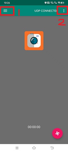
  2. Figure 2 is the main interface of the app

    Among them, choose 1 to see Figure 3.

    • 1: Settings menu;

    • 2: Update apk and rollback apk menu;

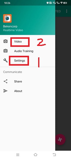
  3. Figure 3 is the setting interface menu

    Among them:

    • 1: For the setting interface as shown in Figure 4;

    • 2: button to return to the main interface;

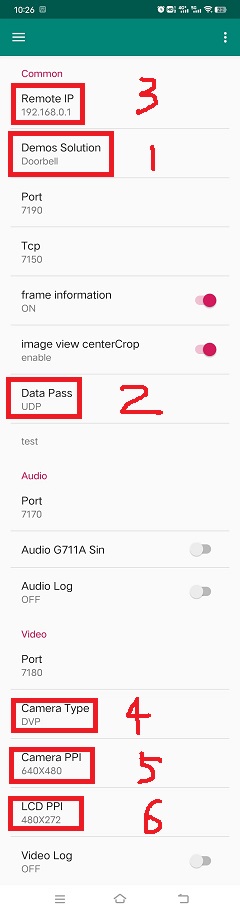
  4. Figure 4 is the real setting interface

    Among them, the setting instructions are as follows, after the setting is completed, return to the main interface of Figure 2

    • 1: Set the solution, currently support video_transfer and doorbell, select doorbell here;

    • 2: Set the data transmission mode, currently supports UDP and TCP, and UDP is selected by default;

    • 3: Set the ip address of the peer, the default is 192.168.0.1 in ap mode, and it is not required to be modified, and in sta mode, it is set to the ip address of the peer;

    • 4: Set the camera type, currently supports DVP and UVC, set according to the type of camera you use;

    • 5: Set the output resolution of the camera;

    • 6: Set the resolution of the LCD output, according to the LCD screen resolution you use;

  5. Figure 5 is the function enable setting interface

    Among them, the function enable description is as follows:

    • 1: Switch video image transmission;

    • 2: switch voice;

    • 3: Photo switch, currently not supported;

    • 4: Switch LCD screen display;

Note

Set the peer IP address in Figure 4. When the board is softap, the default is 192.168.0.1. When the board is used as a staion, the mobile phone and the board are connected to the same ap, and the filled IP address can be passed through the command `` ip`` to get. In addition, the app also supports the function of mobile phone image transfer, that is, the command video_transfer -a|s ssid key, but step 1 in Figure 4 must be set to video_transfer mode. The apk download address: http://dl.bekencorp.com/apk/RealtimeVideo.apk

RealtimeVideo_app

Figure 1. doorbell apk

RealtimeVideo_app_screen

Figure 2. RealtimeVideo_app Main screen

RealtimeVideo_app_set_menu

Figure 3. RealtimeVideo_app Set menu

RealtimeVideo_app_set

Figure 4. RealtimeVideo_app set

RealtimeVideo_function_set

Figure 5. RealtimeVideo_function set

6 Add LCD Adapt

The doorbell project can add new screens according to the needs of users to meet different product needs. For the new driver screen driver code, please refer to ./middleware/driver/lcd Add lcd_xxx.c under the path, such as lcd_st7282.c;

The main configuration process of the newly added driver code is as follows:

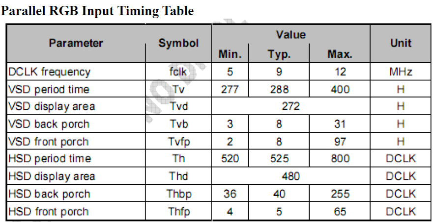
  1. For RGB screen, hsync/vsync proch needs to be modified according to lc

static const lcd_rgb_t lcd_rgb =
{
        .clk = LCD_20M,          //lcd 工作合适的时钟
        .data_out_clk_edge = NEGEDGE_OUTPUT, //rgb输出数据时钟边沿

        .hsync_back_porch = 40,
        .hsync_front_porch = 5,
        .vsync_back_porch = 8,
        .vsync_front_porch = 8,
};
RealtimeVideo_app

Figure 6. rgb sync params config

  1. Induction interface

If the brightness of the screen, the user needs to control the hollow output of the PWM by the PWM control ratio

static void lcd_backlight_open(void)
{
#if CONFIG_PWM
        lcd_driver_backlight_init(LCD_RGB_PWM_BACKLIGHT, 100);
#endif
}

static void lcd_set_backlight(uint8_t percent)
{
#if CONFIG_PWM
        pwm_period_duty_config_t config = {0};

        if (percent > 100)
        {
                percent  = 100;
        }

        config.period_cycle = 100;
        config.duty_cycle = percent;

        bk_pwm_set_period_duty(LCD_RGB_PWM_BACKLIGHT, &config);
#endif
}

If the backlight control of the screen is controlled by GPIO (such as GPIO34) port:

static void lcd_gc9503v_backlight_io_init(void)
{
        gpio_dev_unmap(34);
        bk_gpio_set_capacity(34, 0);
        BK_LOG_ON_ERR(bk_gpio_enable_output(34));
        BK_LOG_ON_ERR(bk_gpio_pull_down(34));
}

static void gc9503v_lcd_backlight_open(void)
{
        BK_LOG_ON_ERR(bk_gpio_pull_up(34));
        // pull up gpio34, enable lcd backlight control
        bk_gpio_set_output_high(34);
}

static void gc9503v_lcd_backlight_close(void)
{
        bk_gpio_set_output_low(34);
}
  1. Initialize screen structure parameters

A screen similar to lcd_st7282 does not need to be initialized, and its structure parameters are initialized as follows:

const lcd_device_t lcd_device_st7282 =
{
        .id = LCD_DEVICE_ST7282, //screen ID num
        .name = "st7282", //screen name
        .type = LCD_TYPE_RGB565, //screen interface type
        .ppi = PPI_480X272, //screen resolution
        .rgb = &lcd_rgb, //Parameter configuration of RGB screen
        .backlight_open = lcd_backlight_open,//register backlight initialization
        .backlight_set = lcd_set_backlight, //Register the light adjustment function
        .init = NULL, //no need to initialize
        .backlight_close = lcd_backlight_close,//register to close the backlight function
        .lcd_off = NULL, //The screen has no off command or off pin
};

The screen resolution is undefined and needs to be defined in ./include/driver/media_types.h. The newly added screen ID needs to be defined in ./include/driver/lcd_types.h, as follows:

typedef enum {
LCD_DEVICE_UNKNOW,
LCD_DEVICE_ST7282,  /**< 480X270  RGB */
LCD_DEVICE_HX8282,  /**< 1024X600 RGB  */
LCD_DEVICE_GC9503V, /**< 480X800 RGB  */
LCD_DEVICE_ST7796S, /**< 320X480 MCU  */
LCD_DEVICE_NT35512,
} lcd_device_id_t;

The screen structure needs to be defined in ./middleware/driver/lcd/lcd_driver.c and declared in ./middleware/driver/lcd/lcd_device.h:

const lcd_device_t *lcd_devices[] =
{
        &lcd_device_st7282,
        &lcd_device_hx8282,
        &lcd_device_st7796s,
        &lcd_device_gc9503v,
        &lcd_device_nt35512
};

extern const lcd_device_t lcd_device_st7282;
extern const lcd_device_t lcd_device_hx8282;
extern const lcd_device_t lcd_device_st7796s;
extern const lcd_device_t lcd_device_gc9503v;
extern const lcd_device_t lcd_device_nt35512;

A screen similar to lcd_gc9503v needs to be initialized, and the initialization function needs to be registered in its structure:

.init = lcd_gc9503v_init,

The lcd_gc9503v_init function is generally provided by the screen manufacturer. It needs the hardware interface to simulate the SPI or I2C interface, so it is necessary to initialize the GPIO and adapt the corresponding SPI or I2C protocol according to the initialization command. Currently, the SPI3-wire and 4-wire protocols have been adapted in the SDK.

void lcd_spi_init_gpio(void)
{
        gpio_dev_unmap(LCD_SPI_RST);
        bk_gpio_set_capacity(LCD_SPI_RST, 0);
        BK_LOG_ON_ERR(bk_gpio_disable_input(LCD_SPI_RST));
        BK_LOG_ON_ERR(bk_gpio_enable_output(LCD_SPI_RST));

        gpio_dev_unmap(LCD_SPI_CLK_GPIO);
        bk_gpio_set_capacity(LCD_SPI_CLK_GPIO, 0);
        BK_LOG_ON_ERR(bk_gpio_disable_input(LCD_SPI_CLK_GPIO));
        BK_LOG_ON_ERR(bk_gpio_enable_output(LCD_SPI_CLK_GPIO));

        gpio_dev_unmap(LCD_SPI_CSX_GPIO);
        bk_gpio_set_capacity(LCD_SPI_CSX_GPIO, 0);
        BK_LOG_ON_ERR(bk_gpio_disable_input(LCD_SPI_CSX_GPIO));
        BK_LOG_ON_ERR(bk_gpio_enable_output(LCD_SPI_CSX_GPIO));

        gpio_dev_unmap(LCD_SPI_SDA_GPIO);
        bk_gpio_set_capacity(LCD_SPI_SDA_GPIO, 0);
        BK_LOG_ON_ERR(bk_gpio_disable_input(LCD_SPI_SDA_GPIO));
        BK_LOG_ON_ERR(bk_gpio_enable_output(LCD_SPI_SDA_GPIO));

        bk_gpio_set_output_high(LCD_SPI_CLK_GPIO);
        bk_gpio_set_output_high(LCD_SPI_CSX_GPIO);
        delay_us(200);
}

So far, the adaptation of the screen driver has been completed.

The next simple adaptation is to ensure that the user enters a command or passes a parameter (screen resolution or name), and the corresponding device can be found in the SDK:

  1. Obtain the judgment of the LCD device name, and add the judgment of the new screen name in media_cli.c

char * get_string_to_name(char *string, char * pre)
{
        char* value = pre;
        if (os_strcmp(string, "nt35512") == 0)
        {
                value = "nt35512";
        }

        .....

        if (os_strcmp(string, "nt35510") == 0)
        {
                value = "nt35510";
        }

        ......

        return value;
}
  1. Obtain the judgment of the pixels of the LCD device, and add the judgment of new pixels in media_cli.c

uint32_t get_string_to_ppi(char *string, uint32_t pre)
{
        uint32_t value = pre;

        if (os_strcmp(string, "1280X720") == 0)
        {
                value = PPI_1280X720;
        }

        .....

        if (os_strcmp(string, "480X854") == 0)
        {
                value = PPI_480X854;
        }

        return value;
}

So far, the adaptation of the screen driver and the adaptation of calling parameters are completed.

Then you can use the new screen display!

lcd_open_t lcd_open;
lcd_open.device_ppi = 480X800;
lcd_open.device_name = "nt35512";
ret = media_app_lcd_open(&lcd_open);

7 png blend

  1. please refer to html/bk7256/zh_CN/latest/examples/video/dma2d.html It introduces in detail the supported types of the data format of the foreground icon. This document explains the common data of ARGB8888 and RGB565.

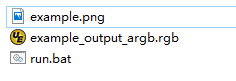
  2. Prepare png or jpg images (also known as foreground images) of small icons that need to be fused

  3. Convert png to rgba8888 data, this conversion can maintain the transparency of png, suitable for blending icons whose background is transparent

  • Toolpath: components/media/tools/ffmpeg_bat/png2argb Access all png images under this path, double-click run.bat.

RealtimeVideo_app

Figure 7. png to rgba8888.rgb

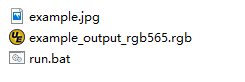
Or convert jpg to rgb565 (big endian) data. During the conversion process, all opaque jpg pixels will be converted to opaque by default, which is suitable for blending icons with similar backgrounds and icon backgrounds, or blending that does not require background frames.

  • Toolpath: components/media/tools/ffmpeg_bat/jpeg2rgb565 Access all png images under this path, double-click run.bat.

RealtimeVideo_app

Figure 8. png to rgb565le.rgb

  1. Use “HxD” or other tools to convert rgb data into a const array and save it in flash.

in “components/media/include/blend_logo.h” Define the foreground image, as well as the length and width of the foreground image:

#define WIFI_LOGO_W 32
#define WIFI_LOGO_H 36

const unsigned char wifi_full_rgb565[2304] = {
        0xFF, 0xFF, 0xFF, 0xFF, 0xFF, 0xFF, 0xFF, 0xFF, 0xFF, 0xFF, 0xFF, 0xFF,
        0xFF, 0xFF, 0xFF, 0xFF, 0xFF, 0xFF, 0xFF, 0xFF, 0xFF, 0xFF, 0xFF, 0xFF,
        ....
};

If you want to fuse the foreground icon at a fixed position on the LCD screen, you also need to set the coordinates of the foreground fusion For example: if you want to merge the foreground icon (16x36) of the version number from the 500th line of the screen (480x800), the center position can be set as follows:

#define VERSION_POSTION_Y   500   //HIGH 800
#define VERSION_POSTION_X   144   //WIDTH 480 "BK7 V1.23.45"  (480-(12*16))/2    12个字节, 图标宽16
  1. DMA2D accomplish blend

After preparing the picture data and the blending position, the next step is to configure the actual blending parameters, please refer to the API interface in lcd_act.c: lcd_blend_handler

For example, the wifi icon to be blended starts to blend at the upper right corner of the screen, that is, the screen coordinates (lcd_width-logo_width, 0), and its lcd_blend.pbg_addr needs to set the address offset (frame->frame + (frame->width - WIFI_LOGO_W) * 2. How to set the offset is described in detail in the DMA2D use case guide.

if ((g_blend_data.lcd_blend_type & LCD_BLEND_WIFI) != 0)
{
        LOGD("lcd wifi blend level =%d \n", g_blend_data.wifi_data);
        lcd_blend.pfg_addr = (uint8_t *)wifi_logo[g_blend_data.wifi_data];
        lcd_blend.pbg_addr = (uint8_t *)(frame->frame + (frame->width - WIFI_LOGO_W) * 2);
        lcd_blend.fg_offline = 0;
        lcd_blend.bg_offline = frame->width - WIFI_LOGO_W;
        lcd_blend.xsize = WIFI_LOGO_W;
        lcd_blend.ysize = WIFI_LOGO_H;
        lcd_blend.fg_alpha_value = FG_ALPHA;
        lcd_blend.fg_data_format = ARGB8888;
        lcd_driver_blend(&lcd_blend);
}

8 Add camera configuration

The cameras used in the application process are not only those currently supported, but also need to be adapted to other dvp cameras or uvc cameras. The following is a separate description of how to adapt to the two different types of cameras.

  1. Adaptation of dvp camera

The dvp camera configures the output of the camera through I2C communication, mainly to configure the value of the sensor register to achieve the expected image effect (resolution, frame rate, etc.)

  1. Refer to the driver code: middleware/driver/camera/dvp_gc0328c.c, first you need to adapt the parameter structure of the dvp camera: dvp_sensor_config_t;

typedef struct
{
        char *name; /**< camera name */
        media_ppi_t def_ppi; /**< The default resolution of the camera, generally used resolution */
        sensor_fps_t def_fps; /**< The camera's default frame rate, usually the commonly used frame rate*/
        uint16 id; /**< camera type (enumeration value, you need to add it yourself), refer to the enumeration type sensor_id_t */
        uint8 clk; /**< The input MCLK specified by the camera protocol, and this MCLK is separated from the CLK of the JPEG module and needs to be configured by yourself */
        /**@example
        * JPEG_96M_MCLK_24M: Indicates that the camera protocol stipulates that the MCLK input is 24MHz,
        and the clock of the JPEG module is 96MHz at this time, and 96MHz can be divided by four to get 24MHz
        * It should also be noted that the working clock of JPEG is divided in CLK (480MHz and 320MHz), the frequency division coefficient range F=[0, 15],
        the frequency division calculation formula JPEG_CLK=CLK/(1+F);
        * JPEG only supports frequency division: 0:4 frequency division, 1:6 frequency division, 2:2 frequency division, 3:3 frequency division
        **/
        uint16 address; /**< The address of the camera through the I2C configuration register, generally the datasheet will tell */
        uint16 fps_cap; /**< The camera supports the configured frame rate, and outputs different frame rates according to requirements */
        uint16 ppi_cap; /**< The camera supports the configured resolution, and outputs different resolutions according to different scenarios */
        bool (*detect)(const dvp_camera_i2c_callback_t *cb); /**< The camera function is automatically detected, which is to read whether the camera ID (such as CHIP_ID) is consistent with the current camera*/
        int (*init)(const dvp_camera_i2c_callback_t *cb); /**< Configure the camera initialization register table, other adjustments (such as: resolution, frame rate, white balance, etc.) must be based on this */
        int (*set_ppi)(const dvp_camera_i2c_callback_t *cb, media_ppi_t ppi); /**< Set the camera resolution register table, generally support different resolution output */
        int (*set_fps)(const dvp_camera_i2c_callback_t *cb, sensor_fps_t fps); /**< The register for setting the camera frame rate, generally supports the output of different frame rates */
        int (*power_down)(const dvp_camera_i2c_callback_t *cb); /**< set register to configure camera enable */
        int (*dump_register)(const dvp_camera_i2c_callback_t *cb, media_ppi_t ppi); /**< Debug interface, view all register configuration values ​​*/
        void (*read_register)(bool enable); /**< Enable the register check interface, check the value of the configuration register is consistent with the expected value during the configuration process*/
} dvp_sensor_config_t;

2) Refer to the enable camera driver code: middleware/driver/camera/dvp_camera.c, in the function: bk_dvp_camera_driver_init(), it may be necessary to add the MCLK input configuration of the new camera;

switch (current_sensor->clk)
{
        case JPEG_96M_MCLK_16M:
                jpeg_config.sys_clk_div = 4;
                jpeg_config.mclk_div = 1;
                break;

        case JPEG_96M_MCLK_24M:
                jpeg_config.sys_clk_div = 4;
                jpeg_config.mclk_div = 0;
                break;

        case JPEG_120M_MCLK_20M:
                jpeg_config.sys_clk_div = 3;
                jpeg_config.mclk_div = 1;
                break;

        case JPEG_120M_MCLK_30M:
                jpeg_config.sys_clk_div = 3;
                jpeg_config.mclk_div = 0;
                break;

        default:
                break;
}

Note

Note: 480MHz is selected by default in the above JPEG gaze, and there is currently no open SDK interface to configure and select 480MHz or 320MHz. If you need to choose 320MHz, please refer to the JPEG driver code: middleware/driver/jpeg_enc/jpeg_driver.c.

static void jpeg_power_config_set(const jpeg_config_t *config)
{
        sys_drv_set_jpeg_clk_sel(1);//0:320MHz, 1:480MHz
        sys_drv_set_clk_div_mode1_clkdiv_jpeg(config->sys_clk_div);
        sys_drv_set_jpeg_disckg(1);
        bk_pm_clock_ctrl(PM_CLK_ID_JPEG, CLK_PWR_CTRL_PWR_UP);
}
  1. Adaptation of uvc camera

    The only thing that uvc needs to adapt to is the resolution it supports. The resolution of uvc output is ever-changing. Currently, only some conventional resolutions are adapted. If customers have special resolutions, they need to add them by themselves.

    1) Currently, customers are not supported to add new resolutions independently, and they will be modified later, because the current addition of new resolutions requires developers to give customers a new libusb.a file. Replace the path: components/bk_libs/bk7256_app/libs /libusb.a

    2) After replacing the new libusb.a file, refer to the header file: include/driver/media_types.h, the parameters in the enumeration type media_ppi_t need to be added, if not.

  2. Add a new resolution to the command line

    If you need to use the cli command that comes with doorbell, you need to make the newly added resolution take effect, otherwise skip this step

    Refer to the doorbell command line: components/media/cli/media_cli.c, adapt the new command, add a new resolution in the function: get_string_to_ppi();

Attention

The width of the camera resolution must be divisible by 16 (864/16), and the height must be divisible by 8 (480/8). Otherwise hardware decoding will fail.

9 LCD Rotate

When the pixels of the screen and the picture are opposite, for example, the screen is 480X800 and the camera is 800X480, the image can be rotated and displayed. Rotated images are currently adapted as follows:

10 font blend

The SDK supports anti-aliasing fusion of fonts. The fonts are provided to users as internal libraries. Currently supported fonts are:

#define FONT_ANTI4BPP_ROBOTO_53           1
#define FONT_ANTI4BPP_BLACK24             1
#define FONT_ANTI4BPP_BLACK48             1
#define FONT_ANTI4BPP_SOURCE_HAN_SANS17   0
#define FONT_ANTI4BPP_SOURCE_HAN_SANS42   0

#if FONT_ANTI4BPP_ROBOTO_53
extern const gui_font_digit_struct *const font_digit_Roboto53;
#endif
#if FONT_ANTI4BPP_SOURCE_HAN_SANS17
extern const gui_font_digit_struct *const font_digitSource_Han_Sans17;
#endif
#if FONT_ANTI4BPP_SOURCE_HAN_SANS42
extern const gui_font_digit_struct *const font_digitSource_Han_Sans42;
#endif
#if FONT_ANTI4BPP_BLACK24
extern const gui_font_digit_struct *const font_digit_black24;
#endif
#if FONT_ANTI4BPP_BLACK48
extern const gui_font_digit_struct *const font_digit_black48;
#endif

Attention

Currently, words are added according to different customer needs. If the customer needs are not met, please contact support.

Please refer to the code of font blend middleware/driver/lcd_driver.c API:lcd_driver_font_blend

font_t font;
font.info = (ui_display_info_struct){rgb565_data,0,lcd_font->ysize,0,{0}};
font.width = lcd_font->xsize;
font.height = lcd_font->ysize;
font.font_fmt = lcd_font->font_format;
for(int i = 0; i < lcd_font->str_num; i++)
{
        font.digit_info = lcd_font->str[i].font_digit_type;
        font.s = lcd_font->str[i].str;
        font.font_color = lcd_font->str[i].font_color;
        font.x_pos = lcd_font->str[i].x_pos;
        font.y_pos = lcd_font->str[i].y_pos;
        lcd_draw_font(&font);
}

The values ​​for each parameter are entered as follows:

//Configuration of blend Locations
frame_addr_offset = ((start_y + VERSION_POSTION_Y) * frame->width + start_x + VERSION_POSTION_X) * 2;
lcd_font_config.pbg_addr = (uint8_t *)(frame->frame + frame_addr_offset);       //address offset
lcd_font_config.bg_offline = frame->width - CLOCK_LOGO_W;
lcd_font_config.xsize = CLOCK_LOGO_W;       ///The width of the fusion/blend area is determined according to the width of Chinese characters
lcd_font_config.ysize = CLOCK_LOGO_H;       ///The height of the fusion area is determined by the height of the Chinese characters
lcd_font_config.str_num = 2;                ///Merge several strings at once
#if 1  ///font yuv data to bg yuv image
if (frame->fmt == PIXEL_FMT_VUYY)           ///Fusion Chinese characters into YUV data
        lcd_font_config.font_format = FONT_VUYY;
else
        lcd_font_config.font_format = FONT_YUYV;
#else  ///font rgb data to bg yuv image
lcd_font_config.font_format = FONT_RGB565;  ///Fusion Chinese characters into RGB565 data
#endif

///White font, font size, blending into the starting coordinates of the area
lcd_font_config.str[0] = (font_str_t){(const char *)("MU, 27℃"), FONT_WHITE, font_digit_black24, 0, 2};
lcd_font_config.str[1] = (font_str_t){(const char *)("2022-12-12 VL"), FONT_WHITE, font_digit_black24, 0, 26};

lcd_font_config.bg_data_format = frame->fmt;  ///background data format
lcd_font_config.bg_width = frame->width;      ///background image size
lcd_font_config.bg_height = frame->height;
lcd_driver_font_blend(&lcd_font_config);