UART User Guide
Summary
UART (Universal Asynchronous Receiver and Transmitter), It is used to realize full duplex or half duplex data exchange between different devices.

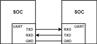
UART Connection
The figure above shows the UART serial port TTL level hardware connection, where:
TXD:For sending data, it should be connected to RXD pin of the receiving device
RXD:For receiving data, it should be connected to the TXD pin of the transmitting device
GND:Provide the same reference level for both parties
Beken chip usually has two UARTs (UART1 and UART2). BK7256 supports three UARTs (UART1, UART2 and UART3). UART2 is used to print debugging information (configurable in menuconfig, default UART2)
UART Config
In order to use UART for data transmission, the following parameters need to be configured:
Baud rate:The number of bits transmitted per second, generally 9600, 19200, 115200, etc
Data bits:There can be 5, 6, 7 or 8 bits of data. Generally, we transmit data by byte (8 bits). The sender changes the status (high level or low level) of the data line bit by bit to send them. When transmitting data, the lowest bit is transmitted first, and the highest bit is transmitted last
Check bit:It is used to verify the correctness of data transmission. It can only detect errors, not correct them
Stop bit:It is used to indicate that the current data transmission is completed, and the logic level is “1”
UART Sequential

UART Timing
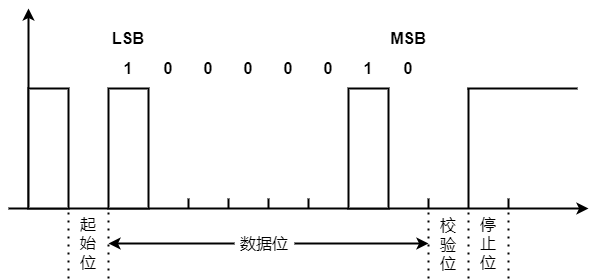
The figure above shows the waveform of sending ‘A’ (0x41) by 8-bit data bit+1-bit even check bit+1-bit stop bit The binary of ‘A’ is 01000001. The small end transmits, that is, the low bit (LSB) comes first and the high bit (MSB) comes last
When idle: the data line is high
Start bit: when data transmission is required, UART will change the state of TXD to low level, usually 1 bit
Data bits: The sender changes the status (high level or low level) of the data line bit by bit and sends them out. Bit [0] is transmitted first, and its value is 1; Then send bit [1], whose value is 0, and so on
Check bit: even check: the number of data bits+bits whose check bit value is “1” is even, so the check bit is low
Stop bit: Since the configured stop bit is 1 bit, the stop bit is 1 bit high
UART Send Packet Channel
Send Packet Channel:
Application can call ‘bk_uart_write_bytes()’ to send packets
UART Packet sent by hardware
Note
When the application packet rate exceeds the UART hardware transmission rate, ‘bk_uart_write_bytes()’ will wait for a busy time, which may affect the CPU performance. But in practical application, this is usually not a problem.
UART Packet Receiving Channel

UART Receive Data
UART The packet receiving channel is shown in the figure above:
UART Hardware receiving packet: UART The hardware receives packets into the hardware FIFO. When the number of packets reaches ‘RX Full Threshold’, the ‘UART RX’ interrupt is reported; When the hardware does not receive packets for a period of time, the ‘UART RX’ Finish interrupt is reported. ‘RX Full Threshold’ can be configured through ‘bk_uart_set_rx_full_threshold()’; The length of time for hardware to judge ‘RX Finish’ can be configured through ‘bk_uart_set_rx_timeout()’.
UART Interrupt packet receiving: When the ‘UART RX’ or ‘UART RX Finish’ interrupt is generated, the software enters the UART interrupt processing function. The UART interrupt reads data from the hardware FIFO and puts it into the RX FIFO. If an application is waiting for data at this time, wake up the application to receive packets. The size of ‘UART RX FIFO’ can be configured through menuconfig.
UART Application package receiving: When the application calls ‘bk_uart_read_bytes()’, it will read data from the UART RX FIFO. When there is no data in the UART RX FIFO, if timeout is set to 0, ‘bk_uart_read_bytes()’ will return immediately. Otherwise, it will wait until timeout or new data is received in the UART RX FIFO.
UART Packet Receiving Flow Control
When the rate of UART interrupt fetching packets from UART HW FIFO is less than the rate of UART hardware filling packets into HW FIFO, UART HW FIFO will be full. If UART hardware flow control is enabled, UART hardware will notify the sender to stop sending, otherwise packet loss will occur.
When the rate of UART application fetching packets from SW FIFO is less than the rate of UART interrupt filling packets into SW FIFO, UART SW FIFO will be full. When the SW FIFO is full, the interrupt will read the data in the hardware FIFO and discard it. At this time, the “rx kfifo is full” log will be displayed. When this happens, the application function may be affected. Generally, the solution is to improve the application processing speed, such as increasing the priority of application tasks.
Note
Another solution to SW FIFO Full is to interrupt and stop fetching packets from HW FIFO, thus triggering hardware packet receiving flow control, and finally realizing packet receiving speed reduction. ARMINO may support this mechanism in the future.
UART Application Scenario
At present, UART supports three different application modes:
Use the default UART interrupt processing flow: The default ‘bk_uart_write_bytes()/bk_uart_read_bytes()’ is used to process UART receiving and sending. The receiving and sending channel is described in the UART receiving channel section. Generally, this method can meet the needs of most applications.
Use the default UART interrupt processing flow and register the user callback: The only difference from the first method is that the user’s registered callback will be called after the UART interrupt is generated.
UART interrupt processing is completely implemented by the application itself: When the default UART interrupt processing flow cannot meet the application requirements, such as the UART of the application is implemented by a third-party code, you can use ‘bk_interrupt_Register(xx, isr, arg)’ replaces the default UART interrupt handler. At this time, the receiving and sending process is completely implemented by the application.