SARADC
Summary
SARADC currently supports up to 14 channels, but only 1-6 channels are currently supported in BK7231N/BK7236/BK7256, 1-7 channels are supported in BK7231U/BK7251/BK7252/bk7253, and 0-13 channels are supported in BK7271; SARADC precision is 12bit by default,Generally, the accuracy is not dynamically adjusted in the SARADC drive.
SARADC Mode Type:
Sleep Mode:
ADC stops any operation in the sleep mode, which is equivalent to the ‘Power Down’ state
Single Step Mode:
In the single step mode, ADC will only collect one data at a time. After the collection, it will automatically change to the sleep mode, and the corresponding mode status bit will also change to the sleep mode. Then wait for MCU to read data, and set the mode to single step mode for each sampling.
Software Control Mode
ADC interrupt will be generated under software control mode. When in this mode, an interrupt will be generated after ADC conversion is completed. At this time, it will wait for MCU to read data. If data is not read, no interrupt will be generated. If MCU reads data, clears the interrupt, ADC starts a new round of conversion, and continues to wait for MCU to read data…
Continuous Mode
The continuous mode is under the software control mode. The wait for MCU to read data is removed. No matter whether MCU fetches data or not, ADC always samples and converts data at a fixed time without being affected by any signal. Only when ADC is stopped can ADC stop reading data.
Note
When ADC is in continuous mode, it will always report interrupts and collect data, which will cause frequent interrupts and affect system performance. Therefore, when ADC is in continuous mode, it is necessary to stop ADC every time the desired ADC data length is reached.
SARADC Data acquisition process:
SARADC Data conversion in continuous mode is shown in the figure below.
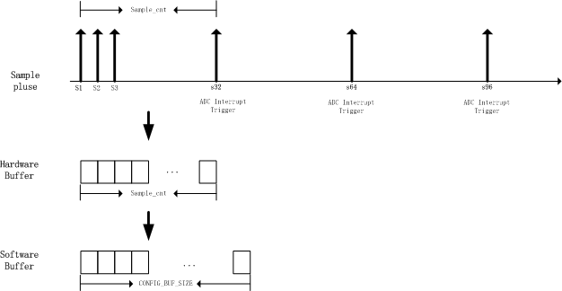
SARADC Overview
As shown in the figure above:
S1,S2:Indicates that the voltage on a channel of ADC is sampled and converted once, and 16 bits of data are output once sampled; The sampling voltage range is 0 to 2.4v; One sampling time is 16 clocks
Sample Rate:The reciprocal of the two sampling intervals is the sampling rate, which only takes effect in continuous mode.
Sample Cnt:It has two meanings. On the one hand, it represents the size of the ADC hardware buffer in 16bits. ADC stores the data obtained from each sampling in the hardware buffer; On the other hand, it also represents the interrupt reporting time point, that is, how many samples are passed to report an interrupt; Sample Cnt It can be configured by API ‘bk_adc_set_sample_cnt()’, and the default value is 32.
ADC Hardware Buffer: That is, the buffer in which the hardware stores the sampling data, with the same size as the Sample Cnt.
- ADC Software Buffer: The ADC driver stores the buffer of sampling data. After each ADC interrupt, the ADC driver copies the data in the ADC Hardware Buffer to the ADC Software Buffer. Generally, the ADC Software Buffer size is not less than the ADC Hardware Buffer
Every call to ‘bk_adc_read()’/’bk_adc_read_raw()’will first clear ADC Software Buffer, and then start ADC sampling until ADC Software Buffer is full.
The specific processing flow of bk_adc_read()/bk_adc_read_raw() in continuous mode is as follows:
ADC Start: bk_adc_read()/bk_adc_read_raw() Start ADC and start sampling.
ADC Hardware sampling:The hardware samples according to the configured ‘sample rate’, and stores each sampling data in ‘Hardware Buffer’.
ADC Interruption generation:When ADC interrupt is generated after sampling ‘sample cnt’ times, ADC driver will transfer the data in ADC ‘Hardware Buffer’ to ADC ‘Software Buffer’, and finally call ‘bk_adc_isr_register()’ to register ‘callback’.
ADC Start: bk_adc_read()/bk_adc_read_raw() Start ADC and start sampling.