PWM
1 功能概述
BK7258总共有2组PWM,每1组6个channel。
1、每组 PWM 的 相邻通道只能任选1路独立输出((0,1)相邻、(2,3)相邻、(4,5)相邻),同时输出会相互干扰。
2、每组 PWM 可实现3个互补输出,如概述中的表格所示,仅可配置 PWMx 的 CH0与CH1, CH2与CH3, CH4与CH5 作为互补输出, 有相应的死区相关的寄存器可配置,较为精准,但通道固定。
3、PWM1 的 CH0, CH2, CH4 与 PWM2 的 CH0, CH2, CH4 任意两通道组成互补输出,软件实现互补功能,较为灵活,但精度不及硬件实现的方式。
4、另外要应用到灯或电机时,P8/P22,p9/P23不建议使用。
bk7258具有12路PWM输出,输出时其时钟源选择的是26M,每一路的周期及占空比可以进行配置,channel如下:
channel
GPIO
channel
GPIO
0
GPIO6/GPIO18
6
GPIO32
1
GPIO7/GPIO19
7
GPIO33
2
GPIO8/GPIO22
8
GPIO34
3
GPIO9/GPIO23
9
GPIO35
4
GPIO24
10
GPIO36
5
GPIO25
11
GPIO37
注:支持多个GPIO时,请注意默认PWM 通道对应的GPIO配置,配置文件在gpio_map.h GPIO_PWM_MAP_TABLE
2 代码路径
demo路径:
components\bk_cli\cli_pwm.c
3 cli命令简介
demo运行依赖的宏配置:
NAME
Description
File
value
CONFIG_PWM
support PWM
middleware\soc\bk7258\bk7258.defconfigy
demo支持的命令如下表:
Command
Param
Description
pwm_driver init {26M|DCO}
26M|DCO:clk source,default 26M
init the resoure common to all PWM channels
pwm_driver deinit
none
free all resource related to pwm
pwm {chan} init {period_v} {duty_v}
[duty2_v][duty3_v]
chan: pwm channel
power up and config the pwm channel, set the period and duty cycle
note: this chip supports 3 duty cycle , parameter duty2_v and duty3_v are optional
period_v:pwm periord
duty_v: duty cycle
duty2_v: second level reversal
duty3_v: third level reversal
pwm {chan} duty {period_v} {duty_v}
[duty2_v] [duty3_v]
chan: pwm channel
configure the period and duty cycle.
note: parameter duty2_v and duty3_v are option.
period_v:pwm periord
duty_v: duty cycl
duty2_v: second level reversal
duty3_v: third level reversal
pwm {chan} {start|stop|deinit}
chan: pwm channel
read data_size bytes of data from
start|stop|deinit:
pwm {chan} signal {low|high}
chan: pwm channel
set the initial signal to high|low
low|high: initial signal level
pwm_group init {chan1} {chan2}
{period} {chan1_duty} {chan2_duty}
chan1: pwm channel
init the PWM group
The PWM group is a channel pair that has following attributes: -The period is same -The initial signal level is opposite -Start and stop at the same time
chan2: pwm channel
period: pwm periord
chan1_duty: chan1 duty cycle
chan2_duty: chan2 duty cycle
pwm_group {start|stop|deinit}
chan: pwm channel
start|stop|deinit the PWM group
start|stop|deinit:
pwm_group config {group} {period}
{chan1_duty} {chan2_duty}
group: pwm channel
Configure the duty and period of a PWM group
period: pwm periord
chan1_duty: chan1 duty cycle
chan2_duty: chan2 duty cycle
pwm_capture {chan} init {pos|neg|edge}
chan: pwm channel
calculate the cycles between two different pos-edge|neg-edge|edges
pos|neg|edge: counting mode
pwm_capture {chan} {start|stop|deinit}
chan: pwm channel
start|stop|deinit pwm capture func
start|stop|deinit
4 演示介绍
demo执行的步骤如下:
1、准备好逻辑分析仪,连接方式如下:
pwm通道0----GPIO18

pwm通道1----GPIO19
2、PWM独立输出模式
对PWM驱动进行初始化:
pwm_driver init
2.1 普通输出
pwm 0 init 200 100 0 0 25 //占空比50%
pwm 0 start
波形如下:
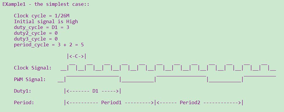
Figure 1. 输出60%占空比的PWM
备注
注意:根据参数的配置,在相同周期内,占空比可以进行调整。但每次调整配置都在下一个周期才会生效; 在PWM进行init和duty设置时,必须 period > (D1+D2+D3)。