LCD
LCD screen is the abbreviation of Liquid Crystal Display. The structure of LCD is to place liquid crystals between two parallel pieces of glass. There are many vertical and horizontal small wires between the two pieces of glass. By controlling whether the rod-shaped crystal molecules are energized or not, the direction is changed, and the light is refracted to create a picture. Liquid crystal is an organic compound composed of long rod-shaped molecules. In their natural state, the long axes of these rod-like molecules are roughly parallel.
LCD physical structure
LCD screen panels are mainly composed of glass substrates, polarizing plates, color filters, liquid crystal materials, alignmentLayer, optical films, drive circuits and other components.
1.glass substrates A glass substrate is actually a thin piece of glass with a flat surface. There is a transparent conductive layer of In2O3 or SnO2 evaporated on the surface, which is the ITO film layer. After photolithography and processing, a transparent conductive pattern is made. These graphics are composed of the smallest image unit, pixel graphics and outer lead graphics of all the chromaticity and brightness of an image. Therefore, the outer leads must not be soldered by traditional soldering. Connections can only be made via conductive rubber strips or conductive tape, etc. If it is scratched, cut or corroded, the device will be scrapped.
2.color filters The reason why the LCD panel can display colors is because the light passes through the color filter. Then the liquid crystal panel is changed by the voltage of the driving chip, so that the liquid crystal molecules stand in a row or appear in a twisted state. After forming the gate, you then choose whether the light from the backlight source penetrates or not, and finally the picture is produced. But this is only a difference in the degree of light transmission, and the colors produced are only black and white. If you want to form a colorful picture, It needs to rely on a combination of three light sources: red, green, and blue.
3.alignment film Alignment film is the most critical material to control the quality of LCD display. In order to achieve a good rotation effect of the liquid crystal material, it is necessary to apply an alignment film on the inside of the upper and lower electrode substrates of the LCD display screen. After the alignment film is coated, the friction process will be carried out. The surface of the alignment film will form a groove arranged in a certain direction due to friction. The liquid crystal material on the alignment film will also reach the desired height due to the force between molecules. A directional effect that produces alignment. In this way, we can control the predetermined direction and predetermined tilt angle arrangement of the liquid crystal molecules, which is very conducive to the movement of the LCD display.
4.liquid crystal material Liquid crystal material is the main material of LCD display screen. Most liquid crystal materials are mixed from several or even more than a dozen types of single liquid crystal materials. Each liquid crystal material has its own fixed clearing point TL and crystallization point TS. Therefore, each type of LCD display must be used or stored within a certain temperature range between TS and TL. If the temperature is too low, crystallization will destroy the orientation layer of the LCD display; and If the temperature is too high, The liquid crystal will lose its liquid crystal state, and then it will lose all the functions of the LCD display.
5.polarizer The main purpose of polarizers is to polarize light that passes through the dichroic medium of the polarizing film.
6.drive circuit The biggest function of the drive circuit is to build on the drive circuit by adjusting a series of parameters such as voltage, phase, peak value, frequency, timing, effective value, duty cycle, etc. applied to the pixel electrode.
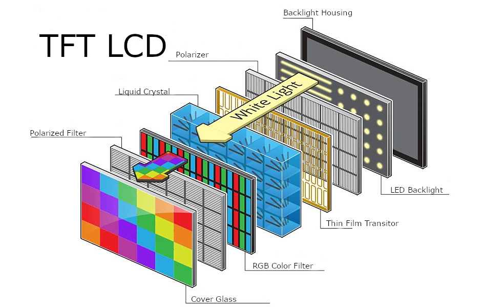
Figure 1. lcd
LCD driver interface
The current mainstream LCD driver interfaces include SPI, I8080, QSPI, RGB, etc.
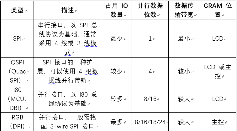
Figure 2. driver interface
8080 LCD hardware interface
The data transmission of the 8080 interface is 8-bit, 9-bit, 16-bit and 18-bit. The interface bus introduced in this document is 8-bit. The hardware schematic diagram is as follows:
3.5”(diagonal), 320x3 RGB x 480 dots, 262K colors TFT LCD module
Driving IC: ST7796S
RGB serial interface
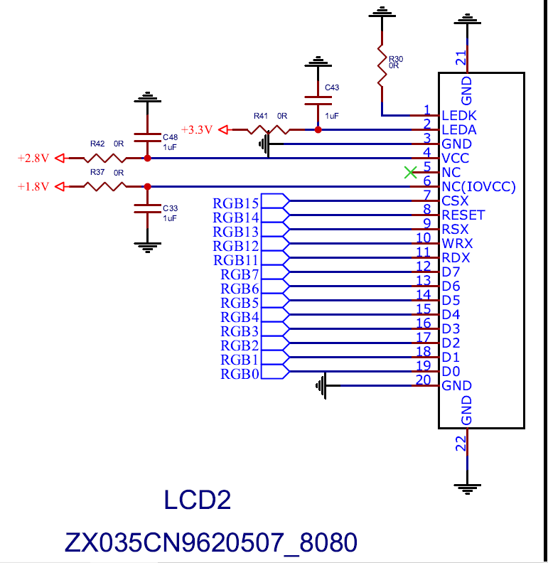
Figure 3. 8080 lcd pin
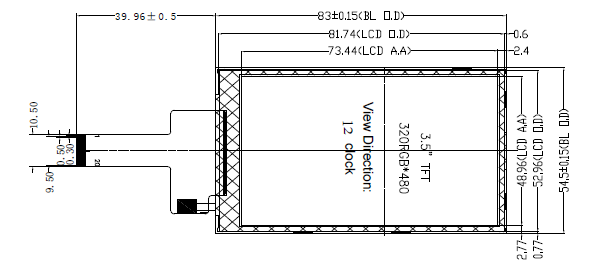
Figure 4. 8080 lcd floor plan
The chip IO resources occupied by the Display 8080 interface are as follows:
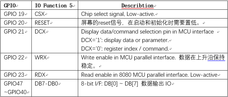
Figure 5. 8080 lcd pin function
8080 LCD interface driving principle
The data transmission of the I8080 protocol is carried out in the format of cmd+parameter. Through the method of cmd + param, the initialization of the screen, the configuration of module functions, and the transmission of image data are realized. The following is a timing diagram for writing commands and data:
RESET is set to 1 when transmitting
When sending DB data, CSX is set low and WRX is pulled low.
If it is COMMAND data, DCX is set low; if it is DATA data, DCX is set high.
During write data transfer, the DB line needs to remain stable on the rising edge of WR.
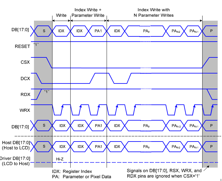
Figure 6. 8080 lcd timing
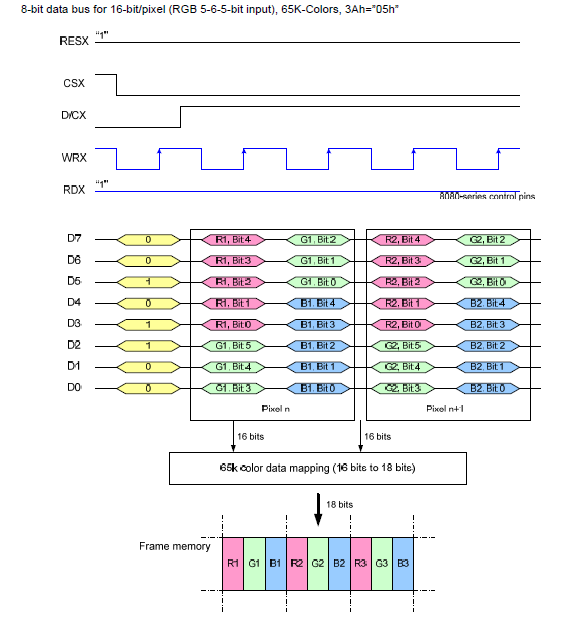
Figure 7. 8080 lcd data transmission
8080 hardware implementation of LCD is as follows:
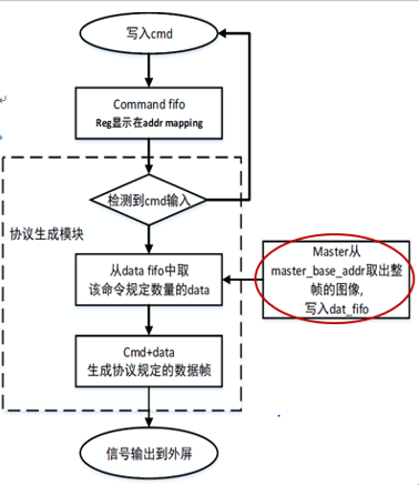
Figure 8. 8080 lcd hardware process
Tearing Effect
The Tearing Effect output line supplies to the MPU a Panel synchronization signal.The signal can be used by the MPU to synchronize Frame Memory Writing when displaying video images. if the lcd not have TE single, the controller should select adapt clk to reduce tearing
RGB LCD hardware interface
The RGB interface, also known as the DPI (Display Pixel Iterface) interface, is a parallel interface that uses ordinary synchronous clock and signal lines to transmit data. The data lines and control lines of its interface are separated. Because there is no GRAM inside the screen, the protocol data speed is fast and the cost is low. The screen can be refreshed directly. It is usually used for driving large screens. The data types of the RGB protocol include RGB565, RGB88, RGB666, etc. The color components are red, green, and blue. By changing the three color channels, the colors are superimposed on each other to obtain a variety of colors. This module uses RGB565 data type.
Resolution : 480(H) x 3(RGB) x 272(V) pixels
Input Data: Parallel RGB565 16-bit
Driver IC: ST7282
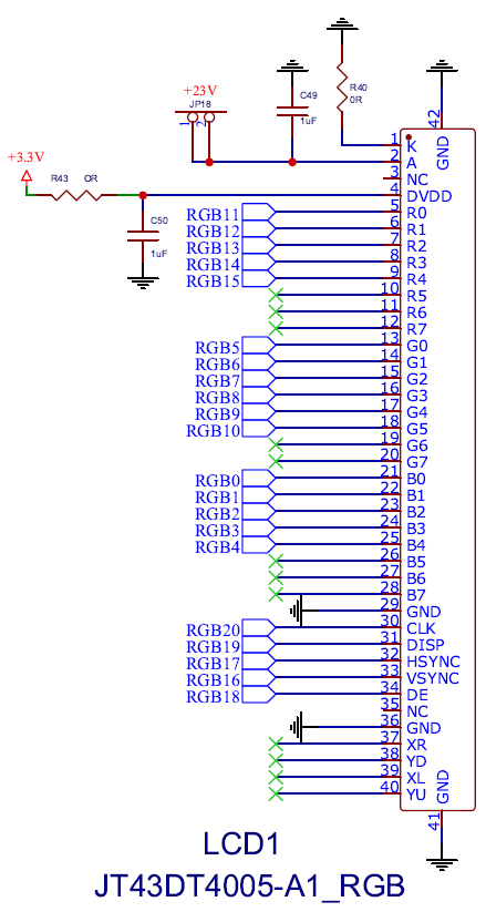
Figure 9. rgb lcd pin
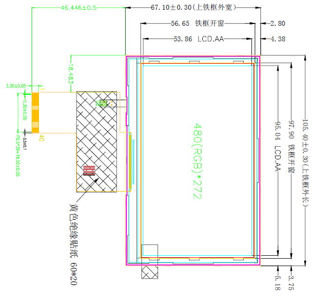
Figure 10. rgb lcd floor plan
The chip IO resources occupied by the Display rgb interface are as follows:
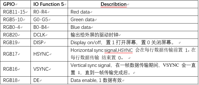
Figure 11. rgb lcd pin function
RGB LCD interface driving principle
The RGB LCD protocol timing diagram is as follows:
DCLK pixel clock signal: output to the driving clock of the external screen to ensure the correctness of data transmission, and read RGB data on the falling edge (or rising edge) of the clock
VSYNC indicates the beginning of scanning a frame. During the data transmission of a frame, VSYNC will be set to 1 until the transmission of a frame is completed.
HSYNC represents the beginning of scanning a line, will be set to 1 before each line of data transmission, and will be set to 0 at the end of each line of data transmission.
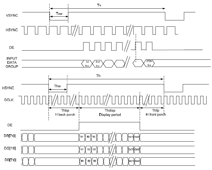
Figure 12. rgb lcd timing
The RGB protocol data format is as follows:
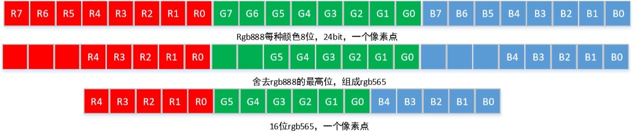
Figure 13. rgb lcd protocol
Hardware implementation of RGB LCD:
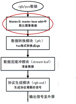
Figure 14. rgb lcd hardware process
QSPI LCD hardware interface
Resolution: 454(W) x RGB x 454(H)
Driver IC: SH8601A
Interface: QSPI
Display mode: MOLED
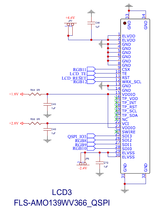
Figure 15. qspi lcd pin
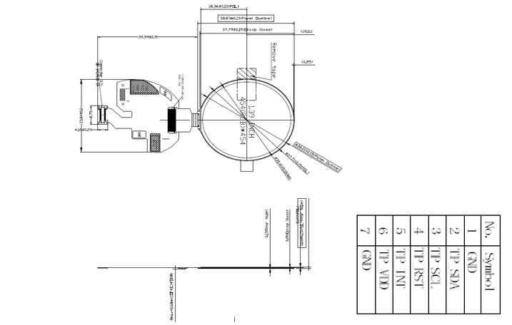
Figure 16. qspi lcd floor plan
The chip IO resources occupied by the Display qspi interface are as follows:
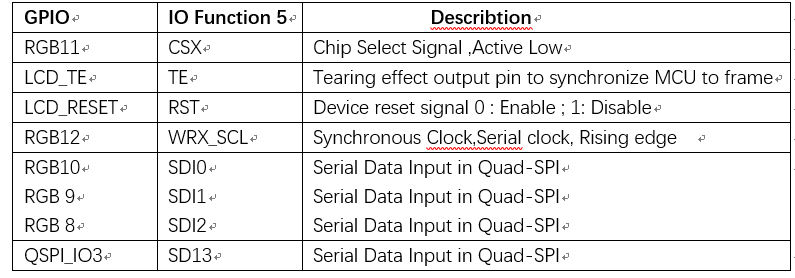
Figure 17. qspi lcd pin function
QSPI LCD interface driving principle
The QSPI LCD protocol timing diagram is as follows:
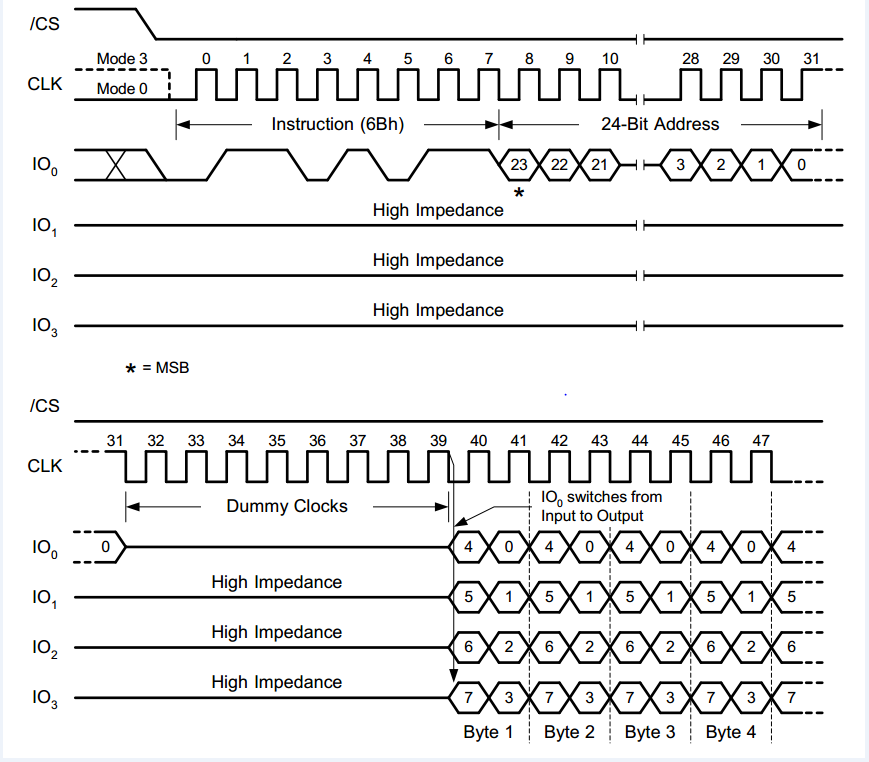
Figure 18. qspi lcd timing
The qspi driver interface is similar to spi. The difference lies in the number of data pins. qspi has two more data transmission pins and is faster than spi.
Hardware implementation of QSPI LCD:
Figure 19. qspi lcd hardware process
software design
The design layering idea of the software code in the project is as follows:
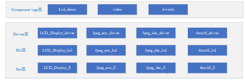
Figure 20. software architecture
Driver layer meaning: For different chip boards, even if the SOC layer is different, the LCD driver interface called is the same. Code design idea: Since the LCD has three different interfaces, the APIs that need to be independently packaged for each interface need to be named 8080_lcd, rgb_lcd, qspi_lcd to distinguish them, while the public API names are not distinguished.
related data structures
enumeration definition of image format:
Figure 21. format enum
enumeration definition of LCD screen device:

Figure 22. lcd device model enumeration
enumeration definition of LCD pixels:

Figure 23. pixel enum
enumeration definition of FPS:

Figure 24. fps enum
code interface
code API as follows:
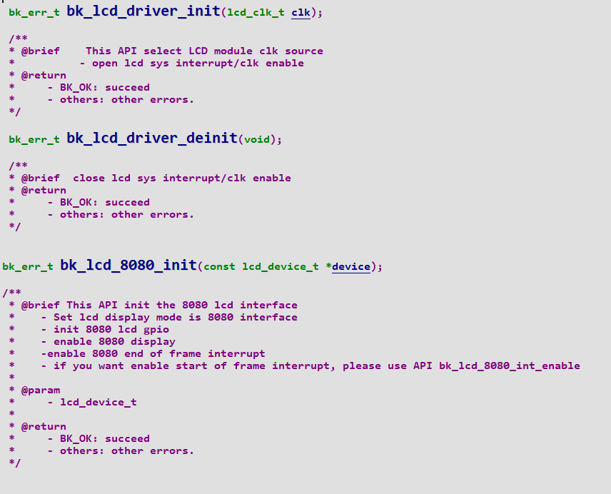
Figure 25. api_1
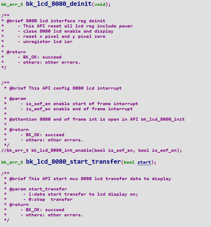
Figure 25. api_2
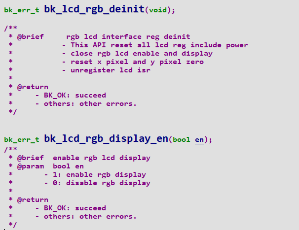
Figure 25. api_3
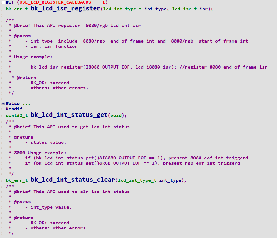
Figure 25. api_4
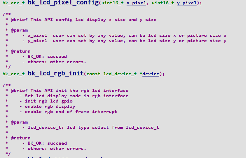
Figure 25. api_5
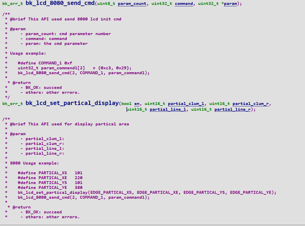
Figure 25. api_6
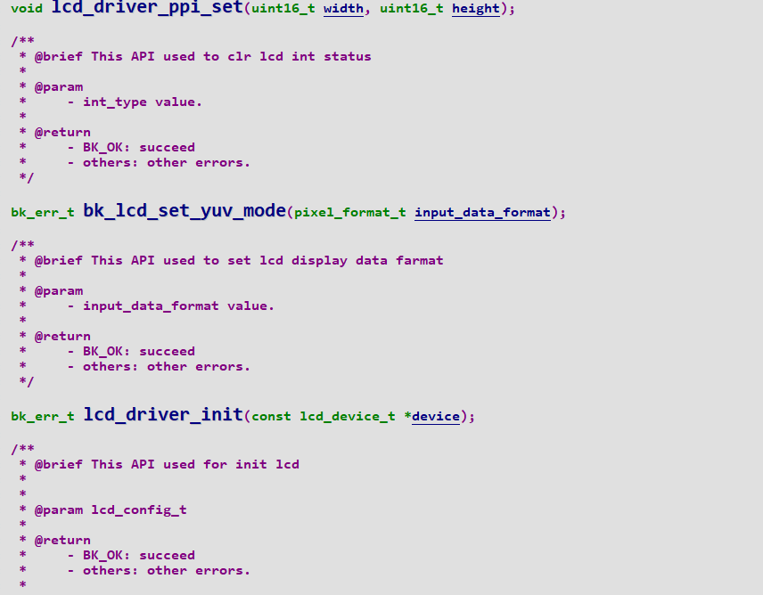
Figure 25. api_7
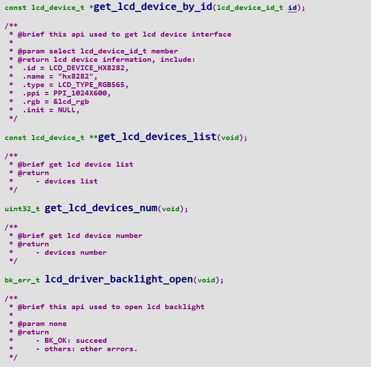
Figure 25. api_8
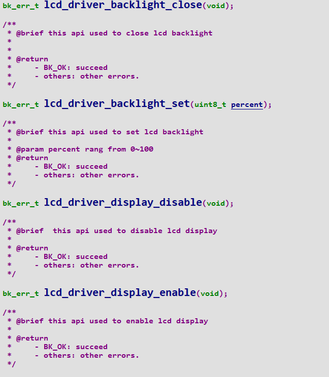
Figure 25. api_9
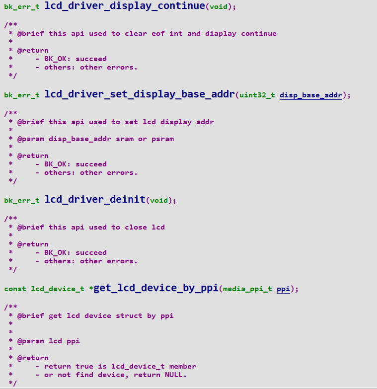
Figure 25. api_10
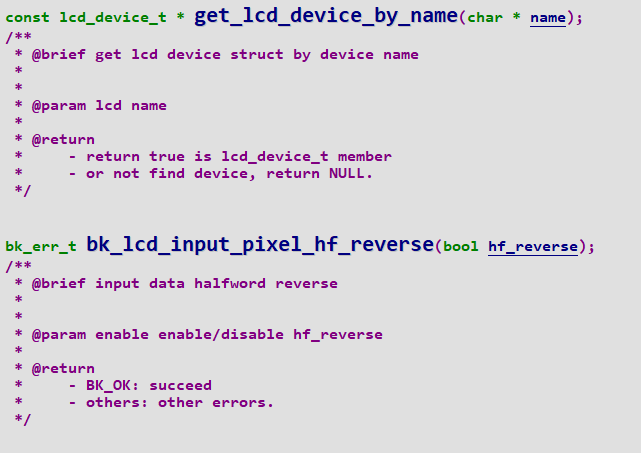
Figure 25. api_11
code configuration process
LCD 8080 configuration flow chart is as follows:
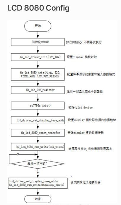
Figure 26. 8080 configuration flow chart
LCD RGB configuration flow chart is as follows:
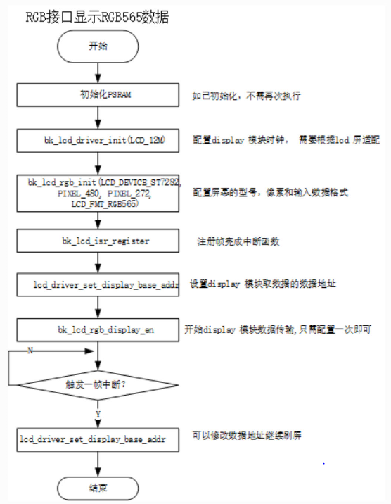
Figure 27. rgb configuration flow chart
The flow chart for setting up special area display is as follows:
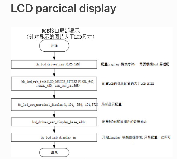
Figure 28. special area configuration diagram
partial display diagram:
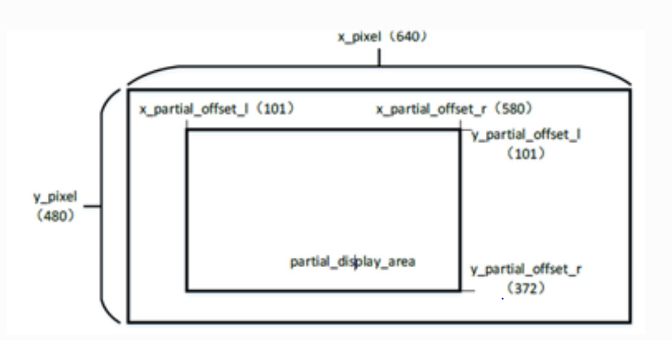
Figure 29. special area display map
for the use of the RGB, please refer to the project “https://docs.bekencorp.com/arminodoc/bk_avdk/bk7258/en/v2.0.1/projects_work/media/lcd_rgb/index.htmll”
for the use of the 8080, please refer to the project “https://docs.bekencorp.com/arminodoc/bk_avdk/bk7258/en/v2.0.1/projects_work/media/lcd_8080/index.html”
for the use of the QSPI, please refer to the project “https://docs.bekencorp.com/arminodoc/bk_avdk/bk7258/en/v2.0.1/projects_work/media/lcd_qspi/index.html”